3.5: Connection-Oriented Transport: TCP
Now that we
have covered the underlying principles of reliable data transfer, let's
turn to TCP--the Internet's transport-layer, connection-oriented, reliable
transport protocol. In this section, we'll see that in order to provide
reliable data transfer, TCP relies on many of the underlying principles
discussed in the previous section, including error detection, retransmissions,
cumulative acknowledgments, timers, and header fields for sequence and
acknowledgment numbers. TCP is defined in RFC 793, RFC 1122, RFC 1323,
RFC 2018, and RFC 2581.
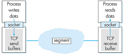
3.5.1: The TCP ConnectionTCP provides multiplexing, demultiplexing, and error detection in exactly the same manner as UDP. Nevertheless, TCP and UDP differ in many ways. The most fundamental difference is that UDP is connectionless, while TCP is connection-oriented. UDP is connectionless because it sends data without ever establishing a connection. TCP is connection-oriented because before one application process can begin to send data to another, the two processes must first "handshake" with each other--that is, they must send some preliminary segments to each other to establish the parameters of the ensuing data transfer. As part of the TCP connection establishment, both sides of the connection will initialize many TCP "state variables" (many of which will be discussed in this section and in Section 3.7) associated with the TCP connection.The TCP "connection" is not an end-to-end TDM or FDM circuit as in a circuit-switched network. Nor is it a virtual circuit (see Chapter 1), as the connection state resides entirely in the two end systems. Because the TCP protocol runs only in the end systems and not in the intermediate network elements (routers and bridges), the intermediate network elements do not maintain TCP connection state. In fact, the intermediate routers are completely oblivious to TCP connections; they see datagrams, not connections. A TCP connection provides for full duplex data transfer. If there is a TCP connection between process A on one host and process B on another host, then application-level data can flow from A to B at the same time as application-level data flows from B to A. A TCP connection is also always point-to-point, that is, between a single sender and a single receiver. So called "multicasting" (see Section 4.8)--the transfer of data from one sender to many receivers in a single send operation--is not possible with TCP. With TCP, two hosts are company and three are a crowd! Let's now take a look at how a TCP connection is established. Suppose a process running in one host wants to initiate a connection with another process in another host. Recall that the process that is initiating the connection is called the client process, while the other process is called the server process. The client application process first informs the client TCP that it wants to establish a connection to a process in the server. Recall from Section 2.6, a Java client program does this by issuing the command: Socket clientSocket = new Socket("hostname", port number); The transport layer in the client then proceeds to establish a TCP connection with the TCP in the server. We will discuss in some detail the connection establishment procedure at the end of this section. For now it suffices to know that the client first sends a special TCP segment; the server responds with a second special TCP segment; and finally the client responds again with a third special segment. The first two segments contain no "payload," that is, no application-layer data; the third of these segments may carry a payload. Because three segments are sent between the two hosts, this connection establishment procedure is often referred to as a three-way handshake. Once a TCP connection is established, the two application processes can send data to each other; because TCP is full-duplex they can send data at the same time. Let us consider the sending of data from the client process to the server process. The client process passes a stream of data through the socket (the door of the process), as described in Section 2.6. Once the data passes through the door, the data is now in the hands of TCP running in the client. As shown in Figure 3.27, TCP directs this data to the connection's send buffer, which is one of the buffers that is set aside during the initial three-way handshake. From time to time, TCP will "grab" chunks of data from the send buffer. Interestingly, the TCP specification [RFC 793] is very "laid back" about specifying when TCP should actually send buffered data, stating that TCP should "send that data in segments at its own convenience." The maximum amount of data that can be grabbed and placed in a segment is limited by the maximum segment size (MSS). The MSS depends on the TCP implementation (determined by the operating system) and can often be configured; common values are 1,500 bytes, 536 bytes, and 512 bytes. (These segment sizes are often chosen in order to avoid IP fragmentation, which will be discussed in the next chapter.) Note that the MSS is the maximum amount of application-level data in the segment, not the maximum size of the TCP segment including headers. (This terminology is confusing, but we have to live with it, as it is well entrenched.)
TCP encapsulates each chunk of client data with a TCP header, thereby forming TCP segments. The segments are passed down to the network layer, where they are separately encapsulated within network-layer IP datagrams. The IP datagrams are then sent into the network. When TCP receives a segment at the other end, the segment's data is placed in the TCP connection's receive buffer. The application reads the stream of data from this buffer. Each side of the connection has its own send buffer and its own receive buffer. The send and receive buffers for data flowing in one direction are shown in Figure 3.27. We see from this discussion that a TCP connection consists of buffers, variables, and a socket connection to a process in one host, and another set of buffers, variables, and a socket connection to a process in another host. As mentioned earlier, no buffers or variables are allocated to the connection in the network elements (routers, bridges, and repeaters) between the hosts.
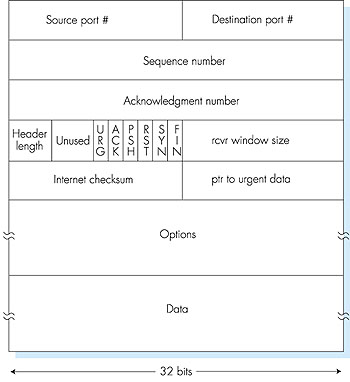
3.5.2: TCP Segment StructureHaving taken a brief look at the TCP connection, let's examine the TCP segment structure. The TCP segment consists of header fields and a data field. The data field contains a chunk of application data. As mentioned above, the MSS limits the maximum size of a segment's data field. When TCP sends a large file, such as an encoded image as part of a Web page, it typically breaks the file into chunks of size MSS (except for the last chunk, which will often be less than the MSS). Interactive applications, however, often transmit data chunks that are smaller than the MSS; for example, with remote login applications like Telnet, the data field in the TCP segment is often only one byte. Because the TCP header is typically 20 bytes (12 bytes more than the UDP header), segments sent by Telnet may only be 21 bytes in length.Figure 3.28 shows the structure of the TCP segment. As with UDP, the header includes source and destination port numbers, that are used for multiplexing/ demultiplexing data from/to upper layer applications. Also, as with UDP, the header includes a checksum field.
A TCP segment header also contains the following fields:
3.5.3: Sequence Numbers and Acknowledgment NumbersTwo of the most important fields in the TCP segment header are the sequence number field and the acknowledgment number field. These fields are a critical part of TCP's reliable data transfer service. But before discussing how these fields are used to provide reliable data transfer, let us first explain what exactly TCP puts in these fields.TCP views data as an unstructured, but ordered, stream of bytes. TCP's use of sequence numbers reflects this view in that sequence numbers are over the stream of transmitted bytes and not over the series of transmitted segments. The sequence number for a segment is the byte-stream number of the first byte in the segment. Let's look at an example. Suppose that a process in host A wants to send a stream of data to a process in host B over a TCP connection. The TCP in host A will implicitly number each byte in the data stream. Suppose that the data stream consists of a file consisting of 500,000 bytes, that the MSS is 1,000 bytes, and that the first byte of the data stream is numbered zero. As shown in Figure 3.29, TCP constructs 500 segments out of the data stream. The first segment gets assigned sequence number 0, the second segment gets assigned sequence number 1000, the third segment gets assigned sequence number 2000, and so on. Each sequence number is inserted in the sequence number field in the header of the appropriate TCP segment.
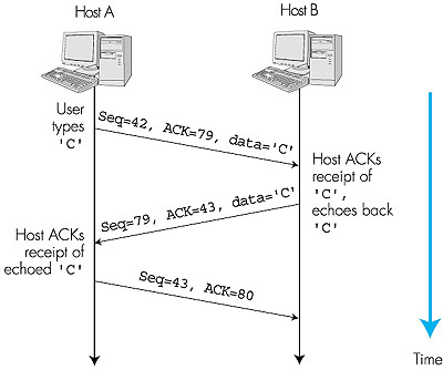
Now let us consider acknowledgment numbers. These are a little trickier than sequence numbers. Recall that TCP is full-duplex, so that host A may be receiving data from host B while it sends data to host B (as part of the same TCP connection). Each of the segments that arrive from host B have a sequence number for the data flowing from B to A. The acknowledgment number that host A puts in its segment is the sequence number of the next byte host A is expecting from host B. It is good to look at a few examples to understand what is going on here. Suppose that host A has received all bytes numbered 0 through 535 from B and suppose that it is about to send a segment to host B. In other words, host A is waiting for byte 536 and all the subsequent bytes in host B's data stream. So host A puts 536 in the acknowledgment number field of the segment it sends to B. As another example, suppose that host A has received one segment from host B containing bytes 0 through 535 and another segment containing bytes 900 through 1,000. For some reason host A has not yet received bytes 536 through 899. In this example, host A is still waiting for byte 536 (and beyond) in order to recreate B's data stream. Thus, A's next segment to B will contain 536 in the acknowledgment number field. Because TCP only acknowledges bytes up to the first missing byte in the stream, TCP is said to provide cumulative acknowledgments. This last example also brings up an important but subtle issue. Host A received the third segment (bytes 900 through 1,000) before receiving the second segment (bytes 536 through 899). Thus, the third segment arrived out of order. The subtle issue is: What does a host do when it receives out-of-order segments in a TCP connection? Interestingly, the TCP RFCs do not impose any rules here and leave the decision up to the people programming a TCP implementation. There are basically two choices: either (1) the receiver immediately discards out-of-order bytes; or (2) the receiver keeps the out-of-order bytes and waits for the missing bytes to fill in the gaps. Clearly, the latter choice is more efficient in terms of network bandwidth, whereas the former choice simplifies the TCP code. Throughout the remainder of this introductory discussion of TCP, we focus on the former implementation, that is, we assume that the TCP receiver discards out-of-order segments. In Figure 3.29 we assumed that the initial sequence number was zero. In truth, both sides of a TCP connection randomly choose an initial sequence number. This is done to minimize the possibility that a segment that is still present in the network from an earlier, already-terminated connection between two hosts is mistaken for a valid segment in a later connection between these same two hosts (who also happen to be using the same port numbers as the old connection) [Sunshine 1978]. 3.5.4: Telnet: A Case Study for Sequence and Acknowledgment NumbersTelnet, defined in RFC 854, is a popular application-layer protocol used for remote login. It runs over TCP and is designed to work between any pair of hosts. Unlike the bulk-data transfer applications discussed in Chapter 2, Telnet is an interactive application. We discuss a Telnet example here, as it nicely illustrates TCP sequence and acknowledgment numbers.Suppose host A initiates a Telnet session with host B. Because host A initiates the session, it is labeled the client, and host B is labeled the server. Each character typed by the user (at the client) will be sent to the remote host; the remote host will send back a copy of each character, which will be displayed on the Telnet user's screen. This "echo back" is used to ensure that characters seen by the Telnet user have already been received and processed at the remote site. Each character thus traverses the network twice between the time the user hits the key and the time the character is displayed on the user's monitor. Now suppose the user types a single letter, 'C', and then grabs a coffee. Let's examine the TCP segments that are sent between the client and server. As shown in Figure 3.30, we suppose the starting sequence numbers are 42 and 79 for the client and server, respectively. Recall that the sequence number of a segment is the sequence number of the first byte in the data field. Thus, the first segment sent from the client will have sequence number 42; the first segment sent from the server will have sequence number 79. Recall that the acknowledgment number is the sequence number of the next byte of data that the host is waiting for. After the TCP connection is established but before any data is sent, the client is waiting for byte 79 and the server is waiting for byte 42.
As shown in Figure 3.30, three segments are sent. The first segment is sent from the client to the server, containing the one-byte ASCII representation of the letter 'C' in its data field. This first segment also has 42 in its sequence number field, as we just described. Also, because the client has not yet received any data from the server, this first segment will have 79 in its acknowledgment number field. The second segment is sent from the server to the client. It serves a dual purpose. First it provides an acknowledgment for the data the server has received. By putting 43 in the acknowledgment field, the server is telling the client that it has successfully received everything up through byte 42 and is now waiting for bytes 43 onward. The second purpose of this segment is to echo back the letter 'C'. Thus, the second segment has the ASCII representation of 'C' in its data field. This second segment has the sequence number 79, the initial sequence number of the server-to-client data flow of this TCP connection, as this is the very first byte of data that the server is sending. Note that the acknowledgment for client-to-server data is carried in a segment carrying server-to-client data; this acknowledgment is said to be piggybacked on the server-to-client data segment. The third segment is sent from the client to the server. Its sole purpose is to acknowledge the data it has received from the server. (Recall that the second segment contained data--the letter 'C'--from the server to the client.) This segment has an empty data field (that is, the acknowledgment is not being piggybacked with any client-to-server data). The segment has 80 in the acknowledgment number field because the client has received the stream of bytes up through byte sequence number 79 and it is now waiting for bytes 80 onward. You might think it odd that this segment also has a sequence number since the segment contains no data. But because TCP has a sequence number field, the segment needs to have some sequence number. 3.5.5: Reliable Data TransferRecall that the Internet's network layer service (IP service) is unreliable. IP does not guarantee datagram delivery, does not guarantee in-order delivery of datagrams, and does not guarantee the integrity of the data in the datagrams. With IP service, datagrams can overflow router buffers and never reach their destination, datagrams can arrive out of order, and bits in the datagram can get corrupted (flipped from 0 to 1 and vice versa). Because transport-layer segments are carried across the network by IP datagrams, transport-layer segments can also suffer from these problems as well.TCP creates a reliable data-transfer service on top of IP's unreliable best-effort service. TCP's reliable data-transfer service ensures that the data stream that a process reads out of its TCP receive buffer is uncorrupted, without gaps, without duplication, and in sequence, that is, the byte stream is exactly the same byte stream that was sent by the end system on the other side of the connection. In this subsection, we provide an overview of how TCP provides a reliable data transfer. We'll see that the reliable data transfer service of TCP uses many of the principles that we studied in Section 3.4. Figure 3.31 shows the three major events related to data transmission/ retransmission at a simplified TCP sender. Let's consider a TCP connection between host A and B and focus on the data stream being sent from host A to host B. At the sending host (A), TCP is passed application-layer data, which it frames into segments and then passes on to IP. The passing of data from the application to TCP and the subsequent framing and transmission of a segment is the first important event that the TCP sender must handle. Each time TCP releases a segment to IP, it starts a timer for that segment. If this timer expires, an interrupt event is generated at host A. TCP responds to the timeout event, the second major type of event that the TCP sender must handle, by retransmitting the segment that caused the timeout. /*assume sender is not constrained by TCP flow or congestion control,
that data from above is less than MSS in size, and that data
transfer is in one direction only
*/
sendbase=initial_sequence number /*see Figure 3.18*/
nextseqnum=initial_sequence number
loop (forever) {
switch(event)
event: data received from application above
create TCP segment with sequence number nextseqnum
start timer for segment nextseqnum
pass segment to IP
nextseqnum=nextseqnum+length(data)
break; /* end of event data received from above */
event: timer timeout for segment with sequence number y
retransmit segment with sequence number y
compute new timeout interval for segment y
restart timer for sequence number y
break; /* end of timeout event */
event: ACK received, with ACK field value of y
if (y > sendbase) {/* cumulative ACK of all date up to y */
cancel all timers for segments with sequence numbers < y
sendbase=y
}
else { /* a duplicate ACK for already ACKed segment */
increment number of duplicate ACKs received for y
if (number of duplicate ACKs received for y==3) {
/* TCP fast retransmit */
resend segment with sequence number y
restart timer for segment y
}
break; /* end of ACK received event */
} /* end of loop forever */
Figure 3.31:
Simplified TCP sender
The third major event that must be handled by the TCP sender is the arrival of an acknowledgment segment (ACK) from the receiver (more specifically, a segment containing a valid ACK field value). Here, the sender's TCP must determine whether the ACK is a first-time ACK for a segment for which the sender has yet to receive an acknowledgment, or a so-called duplicate ACK that re-acknowledges a segment for which the sender has already received an earlier acknowledgment. In the case of the arrival of a first-time ACK, the sender now knows that all data up to the byte being acknowledged has been received correctly at the receiver. The sender can thus update its TCP state variable that tracks the sequence number of the last byte that is known to have been received correctly and in order at the receiver. To understand the sender's response to a duplicate ACK, we must look at why the receiver sends a duplicate ACK in the first place. Table 3.1 summarizes the TCP receiver's ACK generation policy. When a TCP receiver receives a segment with a sequence number that is larger than the next, expected, in-order sequence number, it detects a gap in the data stream--that is, a missing segment. Since TCP does not use negative acknowledgments, the receiver cannot send an explicit negative acknowledgment back to the sender. Instead, it simply re-acknowledges (that is, generates a duplicate ACK for) the last in-order byte of data it has received. If the TCP sender receives three duplicate ACKs for the same data, it takes this as an indication that the segment following the segment that has been ACKed three times has been lost. In this case, TCP performs a fast retransmit [RFC 2581], retransmitting the missing segment before that segment's timer expires. Table 3.1: TCP ACK generation recommendations [RFC 1122, RFC 2581]
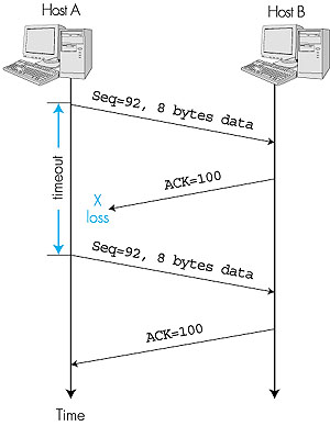
A Few Interesting Scenarios We end this discussion by looking at a few simple scenarios. Figure 3.32 depicts the scenario in which host A sends one segment to host B. Suppose that this segment has sequence number 92 and contains 8 bytes of data. After sending this segment, host A waits for a segment from B with acknowledgment number 100. Although the segment from A is received at B, the acknowledgment from B to A gets lost. In this case, the timer expires, and host A retransmits the same segment. Of course, when host B receives the retransmission, it will observe from the sequence number that the segment contains data that has already been received. Thus, TCP in host B will discard the bytes in the retransmitted segment.
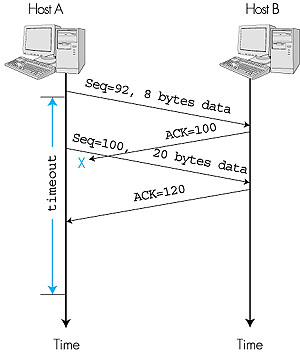
In a second scenario, host A sends two segments back to back. The first segment has sequence number 92 and 8 bytes of data, and the second segment has sequence number 100 and 20 bytes of data. Suppose that both segments arrive intact at B, and B sends two separate acknowledgments for each of these segments. The first of these acknowledgments has acknowledgment number 100; the second has acknowledgment number 120. Suppose now that neither of the acknowledgments arrive at host A before the timeout of the first segment. When the timer expires, host A resends the first segment with sequence number 92. Now, you may ask, does A also resend the second segment? According to the rules described above, host A resends the segment only if the timer expires before the arrival of an acknowledgment with an acknowledgment number of 120 or greater. Thus, as shown in Figure 3.33, if the second acknowledgment does not get lost and arrives before the timeout of the second segment, A does not resend the second segment.
In a third and final scenario, suppose host A sends the two segments, exactly as in the second example. The acknowledgment of the first segment is lost in the network, but just before the timeout of the first segment, host A receives an acknowledgment with acknowledgment number 120. Host A therefore knows that host B has received everything up through byte 119; so host A does not resend either of the two segments. This scenario is illustrated in the Figure 3.34.
Recall that in the previous section we said that TCP is a Go-Back-N style protocol. This is because acknowledgments are cumulative and correctly received but out-of-order segments are not individually ACKed by the receiver. Consequently, as shown in Figure 3.31 (see also Figure 3.18), the TCP sender need only maintain the smallest sequence number of a transmitted but unacknowledged byte (sendbase) and the sequence number of the next byte to be sent (nextseqnum). But the reader should keep in mind that although the reliable data-transfer component of TCP resembles Go-Back-N, it is by no means a pure implementation of Go-Back-N. To see that there are some striking differences between TCP and Go-Back-N, consider what happens when the sender sends a sequence of segments 1, 2, . . ., N, and all of the segments arrive in order without error at the receiver. Further suppose that the acknowledgment for packet n < N gets lost, but the remaining N - 1 acknowledgments arrive at the sender before their respective timeouts. In this example, Go-Back-N would retransmit not only packet n, but also all of the subsequent packets n + 1, n + 2, . . ., N. TCP, on the other hand, would retransmit at most, one segment, namely, segment n. Moreover, TCP would not even retransmit segment n if the acknowledgment for segment n + 1 arrives before the timeout for segment n. There have recently been several proposals [RFC 2018; Fall 1996; Mathis 1996] to extend the TCP ACKing scheme to be more similar to a selective repeat protocol. The key idea in these proposals is to provide the sender with explicit information about which segments have been received correctly, and which are still missing at the receiver. 3.5.6: Flow ControlRecall that the hosts on each side of a TCP connection each set aside a receive buffer for the connection. When the TCP connection receives bytes that are correct and in sequence, it places the data in the receive buffer. The associated application process will read data from this buffer, but not necessarily at the instant the data arrives. Indeed, the receiving application may be busy with some other task and may not even attempt to read the data until long after it has arrived. If the application is relatively slow at reading the data, the sender can very easily overflow the connection's receive buffer by sending too much data too quickly. TCP thus provides a flow-control service to its applications to eliminate the possibility of the sender overflowing the receiver's buffer. Flow control is thus a speed matching service--matching the rate at which the sender is sending to the rate at which the receiving application is reading. As noted earlier, a TCP sender can also be throttled due to congestion within the IP network; this form of sender control is referred to as congestion control, a topic we will explore in detail in Sections 3.6 and 3.7. Even though the actions taken by flow and congestion control are similar (the throttling of the sender), they are obviously taken for very different reasons. Unfortunately, many authors use the term interchangeably, and the savvy reader would be careful to distinguish between the two cases. Let's now discuss how TCP provides its flow-control service.TCP provides flow control by having the sender maintain a variable called the receive window. Informally, the receive window is used to give the sender an idea about how much free buffer space is available at the receiver. In a full-duplex connection, the sender at each side of the connection maintains a distinct receive window. The receive window is dynamic; that is, it changes throughout a connection's lifetime. Let's investigate the receive window in the context of a file transfer. Suppose that host A is sending a large file to host B over a TCP connection. Host B allocates a receive buffer to this connection; denote its size by RcvBuffer. From time to time, the application process in host B reads from the buffer. Define the following variables: LastByteRead = the number of the last byte in the data stream read from the buffer by the application process in B.Because TCP is not permitted to overflow the allocated buffer, we must have: LastByteRcvd - LastByteRead <= RcvBuffer The receive window, denoted RcvWindow, is set to the amount of spare room in the buffer: RcvWindow = RcvBuffer - [LastByteRcvd - LastByteRead] Because the spare room changes with time, RcvWindow is dynamic. The variable RcvWindow is illustrated in Figure 3.35.
How does the connection use the variable RcvWindow to provide the flow control service? Host B tells host A how much spare room it has in the connection buffer by placing its current value of RcvWindow in the window field of every segment it sends to A. Initially, host B sets RcvWindow = RcvBuffer. Note that to pull this off, host B must keep track of several connection-specific variables. Host A in turn keeps track of two variables, LastByteSent and LastByteAcked, which have obvious meanings. Note that the difference between these two variables, LastByteSent - LastByteAcked, is the amount of unacknowledged data that A has sent into the connection. By keeping the amount of unacknowledged data less than the value of RcvWindow, host A is assured that it is not overflowing the receive buffer at host B. Thus, host A makes sure throughout the connection's life that LastByteSent
- LastByteAcked There is one minor technical problem with this scheme. To see this, suppose host B's receive buffer becomes full so that RcvWindow = 0. After advertising RcvWindow = 0 to host A, also suppose that B has nothing to send to A. As the application process at B empties the buffer, TCP does not send new segments with new RcvWindows to host A--TCP will send a segment to host A only if it has data to send or if it has an acknowledgment to send. Therefore, host A is never informed that some space has opened up in host B's receive buffer: host A is blocked and can transmit no more data! To solve this problem, the TCP specification requires host A to continue to send segments with one data byte when B's receive window is zero. These segments will be acknowledged by the receiver. Eventually the buffer will begin to empty and the acknowledgments will contain a nonzero RcvWindow value. Having described TCP's flow-control service, we briefly mention here that UDP does not provide flow control. To understand the issue here, consider sending a series of UDP segments from a process on host A to a process on host B. For a typical UDP implementation, UDP will append the segments (more precisely, the data in the segments) in a finite-size queue that "precedes" the corresponding socket (that is, the door to the process). The process reads one entire segment at a time from the queue. If the process does not read the segments fast enough from the queue, the queue will overflow and segments will get lost. Following this section we provide an interactive Java applet that should provide significant insight into the TCP receive window. Click here to open it in a new window, or select it from the menu bar at the left. 3.5.7: Round Trip Time and TimeoutRecall that when a host sends a segment into a TCP connection, it starts a timer. If the timer expires before the host receives an acknowledgment for the data in the segment, the host retransmits the segment. The time from when the timer is started until when it expires is called the timeout of the timer. A natural question is, how large should timeout be? Clearly, the timeout should be larger than the connection's round-trip time, that is, the time from when a segment is sent until it is acknowledged. Otherwise, unnecessary retransmissions would be sent. But the timeout should not be much larger than the round-trip time; otherwise, when a segment is lost, TCP would not quickly retransmit the segment, and it would thereby introduce significant data transfer delays into the application. Before discussing the timeout interval in more detail, let's take a closer look at the round-trip time (RTT). The discussion below is based on the TCP work in [Jacobson 1988].Estimating the Average Round-Trip Time The sample RTT, denoted SampleRTT, for a segment is the amount of time from when the segment is sent (that is, passed to IP) until an acknowledgment for the segment is received. Each segment sent will have its own associated SampleRTT. Obviously, the SampleRTT values will fluctuate from segment to segment due to congestion in the routers and to the varying load on the end systems. Because of this fluctuation, any given SampleRTT value may be atypical. In order to estimate a typical RTT, it is therefore natural to take some sort of average of the SampleRTT values. TCP maintains an average, called EstimatedRTT, of the SampleRTT values. Upon receiving an acknowledgment and obtaining a new SampleRTT, TCP updates EstimatedRTT according to the following formula: EstimatedRTT = (1 - x) EstimatedRTT + x SampleRTT. The above formula is written in the form of a programming language statement--the new value of EstimatedRTT is a weighted combination of the previous value of EstimatedRTT and the new value for SampleRTT. A typical value of x is x = 0.125 (i.e., 1/8), in which case the above formula becomes: EstimatedRTT = 0.875 EstimatedRTT + 0.125 SampleRTT. Note that EstimatedRTT is a weighted average of the SampleRTT values. As we will see in the homework, this weighted average puts more weight on recent samples than on old samples, This is natural, as the more recent samples better reflect the current congestion in the network. In statistics, such an average is called an exponential weighted moving average (EWMA). The word "exponential" appears in EWMA because the weight of a given SampleRTT decays exponentially fast as the updates proceed. In the homework problems you will be asked to derive the exponential term in EstimatedRTT. Figure 3.36 shows the SampleRTT values (dotted line) and EstimatedRTT (solid line) for a value of x = 1/8 for a TCP connection between void.cs.umass.edu (in Amherst, Massachusetts) to maria.wustl.edu (in St. Louis, Missouri). Clearly, the variations in the SampleRTT are smoothed out in the computation of the EstimatedRTT.
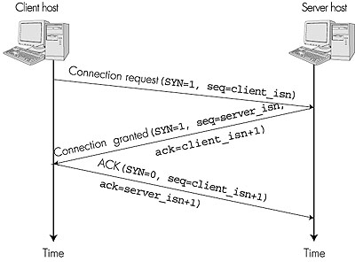
Setting the Timeout The timeout should be set so that a timer expires early (that is, before the delayed arrival of a segment's ACK) only on rare occasions. It is therefore natural to set the timeout equal to the EstimatedRTT plus some margin. The margin should be large when there is a lot of fluctuation in the SampleRTT values; it should be small when there is little fluctuation. TCP uses the following formula: Timeout = EstimatedRTT + 4Deviation,where Deviation is an estimate of how much SampleRTT typically deviates from EstimatedRTT: Note that Deviation is an EWMA of how much SampleRTT deviates from EstimatedRTT. If the SampleRTT values have little fluctuation, then Deviation is small and Timeout is hardly more than EstimatedRTT; on the other hand, if there is a lot of fluctuation, Deviation will be large and Timeout will be much larger than EstimatedRTT. "A Quick Tour around TCP" [Cela 2000] provides nifty interactive applets illustrating RTT variance estimation.Deviation = (1 - x) Deviation + x | SampleRTT - EstimatedRTT | 3.5.8: TCP Connection ManagementIn this subsection, we take a closer look at how a TCP connection is established and torn down. Although this topic may not seem particularly exciting, it is important because TCP connection establishment can significantly add to perceived delays (for example, when surfing the Web). Let's now take a look at how a TCP connection is established. Suppose a process running in one host (client) wants to initiate a connection with another process in another host (server). The client application process first informs the client TCP that it wants to establish a connection to a process in the server. The TCP in the client then proceeds to establish a TCP connection with the TCP in the server in the following manner:
All good things must come to an end, and the same is true with a TCP connection. Either of the two processes participating in a TCP connection can end the connection. When a connection ends, the "resources" (that is, the buffers and variables) in the hosts are de-allocated. As an example, suppose the client decides to close the connection, as shown in Figure 3.38. The client application process issues a close command. This causes the client TCP to send a special TCP segment to the server process. This special segment has a flag bit in the segment's header, the so-called FIN bit (see Figure 3.38), set to 1. When the server receives this segment, it sends the client an acknowledgment segment in return. The server then sends its own shut-down segment, which has the FIN bit set to 1. Finally, the client acknowledges the server's shut-down segment. At this point, all the resources in the two hosts are now de-allocated.
During the life of a TCP connection, the TCP protocol running in each host makes transitions through various TCP states. Figure 3.39 illustrates a typical sequence of TCP states that are visited by the client TCP. The client TCP begins in the closed state. The application on the client side initiates a new TCP connection (by creating a Socket object in our Java examples from Chapter 2). This causes TCP in the client to send a SYN segment to TCP in the server. After having sent the SYN segment, the client TCP enters the SYN_SENT state. While in the SYN_SENT state, the client TCP waits for a segment from the server TCP that includes an acknowledgment for the client's previous segment as well as the SYN bit set to 1. Once having received such a segment, the client TCP enters the ESTABLISHED state. While in the ESTABLISHED state, the TCP client can send and receive TCP segments containing payload (that is, application-generated) data.
Suppose that the client application decides it wants to close the connection. (Note that the server could also choose to close the connection.) This causes the client TCP to send a TCP segment with the FIN bit set to 1 and to enter the FIN_WAIT_1 state. While in the FIN_WAIT_1 state, the client TCP waits for a TCP segment from the server with an acknowledgment. When it receives this segment, the client TCP enters the FIN_WAIT_2 state. While in the FIN_WAIT_2 state, the client waits for another segment from the server with the FIN bit set to 1; after receiving this segment, the client TCP acknowledges the server's segment and enters the TIME_WAIT state. The TIME_WAIT state lets the TCP client resend the final acknowledgment in case the ACK is lost. The time spent in the TIME_WAIT state is implementation-dependent, but typical values are 30 seconds, 1 minute, and 2 minutes. After the wait, the connection formally closes and all resources on the client side (including port numbers) are released. Figure 3.40 illustrates the series of states typically visited by the server-side TCP, assuming the client begins connection tear down. The transitions are self-explanatory. In these two state-transition diagrams, we have only shown how a TCP connection is normally established and shut down. We have not described what happens in certain pathological scenarios, for example, when both sides of a connection want to shut down at the same time. If you are interested in learning about this and other advanced issues concerning TCP, you are encouraged to see Stevens' comprehensive book [Stevens 1994].
This completes our introduction to TCP. In Section 3.7 we will return to TCP and look at TCP congestion control in some depth. Before doing so, however, we first step back and examine congestion-control issues in a broader context. |


 RcvWindow