4.4: Internet Protocol
| So far in this
chapter we've focused on underlying principles of the network layer, without
reference to any specific network architecture. We've discussed various
network-layer service models, the routing algorithms commonly used to deter
mine paths between source and destination, and the use of hierarchy to
address the problem of scale. In this section, we turn our attention to
the network layer of the Internet, the pieces of which are often collectively
referred to as the IP layer (named after the Internet's IP protocol). We'll
see, though, that the IP protocol itself is just one piece (albeit a very
important piece) of the Internet's network layer.
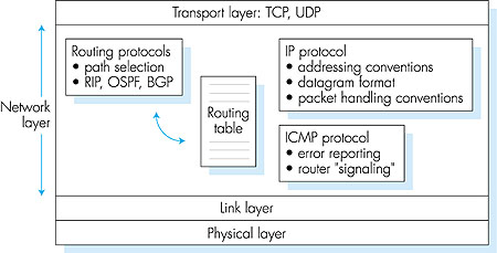
As noted in Section 4.1, the Internet's network layer provides connectionless datagram service rather than virtual-circuit service. When the network layer at the sending host receives a segment from the transport layer, it encapsulates the segment within an IP datagram, writes the destination host address as well as other fields in the datagram, and sends the datagram to the first router on the path toward the destination host. Our analogy from Chapter 1 was that this process is similar to a person writing a letter, inserting the letter in an envelope, writing the destination address on the envelope, and dropping the envelope into a mailbox. Neither the Internet's network layer nor the postal service make any preliminary contact with the destination before moving its "parcel" (datagram or letter, respectively) toward the destination. Furthermore, as discussed in Section 4.1, the Internet's network-layer service and the postal delivery service both provide so-called best-effort service: neither guarantee that a parcel will arrive within a certain time at the destination, nor does either guarantee that a series of parcels will arrive in the order sent. Indeed, neither even guarantee that a parcel will ever arrive at its destination! As shown in Figure 4.14, the network layer in a datagram-oriented network such as the Internet has three major components.
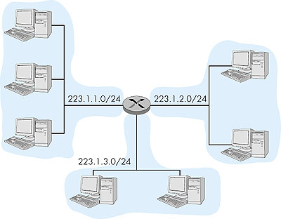
4.4.1: IPv4 AddressingLet's begin our study of IPv4 by considering IPv4 addressing. Although addressing may seem a rather straightforward and perhaps tedious topic, the coupling between addressing and network-layer routing is both crucial and subtle. Excellent treatments of IPv4 addressing are [Semeria 1996] and the first chapter in [Stewart 1999].Before discussing IP addressing, however, we'll need to say a few words about how hosts and routers are connected into the network. A host typically has only a single link into the network. When IP in the host wants to send a datagram, it will do so over this link. The boundary between the host and the physical link is called an interface. A router, on the other hand, is fundamentally different from a host. Because a router's job is to receive a datagram on an "incoming" link and forward the datagram on some "outgoing" link, a router necessarily has two or more links to which it is connected. The boundary between the router and any one of its links is also called an interface. A router thus has multiple interfaces, one for each of its links. Because every host and router is capable of sending and receiving IP datagrams, IP requires each interface to have an IP address. Thus, an IP address is technically associated with an interface, rather than with the host or router containing that interface Each IP address is 32 bits long (equivalently, four bytes), and there are thus a total of 232 possible IP addresses. These addresses are typically written in so-called dotted-decimal notation, in which each byte of the address is written in its decimal form and is separated by a period ("dot") from other bytes in the address. For example, consider the IP address 193.32.216.9. The 193 is the decimal equivalent of the first eight bits of the address; the 32 is the decimal equivalent of the second eight bits of the address, and so on. Thus, the address 193.32.216.9 in binary notation is: 11000001 00100000 11011000 00001001. Each interface on every host and router in the global Internet must have an IP address that is globally unique. These addresses cannot be chosen in a willy-nilly manner, however. To a large extent, an interface's IP address will be determined by the "network" to which it is connected. In this context, the term "network" does not refer to the general infrastructure of hosts, routers, and links that make up a network. Instead, the term has a very precise meaning that is closely tied to IP addressing, as we will see. Figure 4.15 provides an example of IP addressing and interfaces. In this figure, one router (with three interfaces) is used to interconnect seven hosts. Take a close look at the IP addresses assigned to the host and router interfaces; there are several things to be noted. The three hosts in the upper-left portion of Figure 4.15, and the router interface to which they are connected all have an IP address of the form 223.1.1.xxx. That is, they share a common leftmost 24 bits of their IP address. They are also interconnected to each other by a single physical link (in this case, a broadcast link such as an Ethernet cable to which they are all physically attached) with no intervening routers. In the jargon of IP, the interfaces in these hosts and the upper-left interface in the router form an IP network or more simply a network. The 24 address bits that they share in common constitute the network portion of their IP address; the remaining eight bits are the host portion of the IP address. (We would prefer to use the terminology "interface part of the address" rather than "host part of the address" because an IP address is really for an interface rather than a host; but the terminology "host part" is commonly used in practice.) The network itself also has an address: 223.1.1.0/24, where the "/24" notation, sometimes known as a network mask, indicates that the leftmost 24 bits of the 32-bit quantity define the network address. These leftmost bits that define the network address are also often referred to as the network prefix. The network 223.1.1.0/24 thus consists of the three host interfaces (223.1.1.1, 223.1.1.2, and 223.1.1.3) and one router interface (223.1.1.4). Any additional hosts attached to the 223.1.1.0/24 network would be required to have an address of the form 223.1.1.xxx. There are two additional networks shown in Figure 4.15: the 223.1.2.0/24 network and the 223.1.3.0/24 network. Figure 4.16 illustrates the three IP networks present in Figure 4.15.
The IP definition of a "network" is not restricted to Ethernet segments that connect multiple hosts to a router interface. To get some insight here, consider Figure 4.17, which shows three routers that are interconnected with each other by point-to-point links. Each router has three interfaces, one for each point-to-point link, and one for the broadcast link that directly connects the router to a pair of hosts. What IP networks are present here? Three networks, 223.1.1.0/24, 223.1.2.0/24, and 223.1.3.0/24 are similar in spirit to the networks we encountered in Figure 4.15. But note that there are three additional networks in this example as well: one network, 223.1.9.0/24, for the interfaces that connect routers R1 and R2; another network, 223.1.8.0/24, for the interfaces that connect routers R2 and R3; and a third network, 223.1.7.0/24, for the interfaces that connect routers R3 and R1.
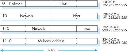
For a general interconnected system of routers and hosts, we can use the following recipe to define the networks in the system. We first detach each interface from its host or router. This creates islands of isolated networks, with interfaces terminating the endpoints of the isolated networks. We then call each of these isolated networks a network. If we apply this procedure to the interconnected system in Figure 4.17, we get six islands or networks. The current Internet consists of millions of such networks. The notion of a network and a network address is an important one, and plays a central role in the Internet's routing architecture. Now that we have defined a network, we are ready to discuss IP addressing in more detail. The original Internet addressing architecture defined four classes of address, as shown in Figure 4.18. A fifth address class, beginning with 11110, was reserved for future use. For a class A address, the first eight bits identify the network, and the last 24 bits identify the interface within that network. Thus, within class A we can have up to 27 networks (the first of the eight bits is fixed as 0), each with up to 224 interfaces. The class B address space allows for 214 networks, with up to 216 interfaces within each network. A class C address uses 21 bits to identify the network and leaves only eight bits for the interface identifier. Class D addresses are reserved for so-called multicast addresses; we'll defer our discussion of class D addresses until Section 4.7.
The four address classes shown in Figure 4.18 (sometimes known as classful addressing) are no longer formally part of the IP addressing architecture. The requirement that the network portion of an IP address be exactly one, two, or three bytes long turned out to be problematic for supporting the rapidly growing number of organizations with small and medium-sized networks. A class C (/24) network could only accommodate up to 28 - 2 = 254 hosts (two of the 28 = 256 addresses are reserved for special use)--too small for many organizations. However, a class B (/16) network, which supports up 65,634 hosts was too large. Under classful addressing, an organization with, say, 2,000 hosts was typically allocated a class B (/16) network address. This led to a rapid depletion of the class B address space and poor utilization of the assigned address space. For example, the organization that used a class B address for its 2,000 hosts was allocated enough of the address space for up to 65,534 interfaces--leaving more than 63,000 unused addresses that could not be used by other organizations. In 1993, the IETF standardized on Classless Interdomain Routing (CIDR--pronounced the same as "cider") [RFC 1519]. With so-called CIDRized network addresses, the network part of an IP address can be any number of bits long, rather than being constrained to 8, 16, or 24 bits. A CIDRized network address has the dotted-decimal form a.b.c.d/x, where x indicates the number of leading bits in the 32-bit quantity that constitutes the network portion of the address. In our example above, the organization needing to support 2,000 hosts could be allocated a block of only 2,048 host addresses of the form a.b.c.d/21, allowing the approximately 63,000 addresses that would have been allocated and unused under classful addressing to be allocated to a different organization. In this case, the first 21 bits specify the organization's network address and are common in the IP addresses of all hosts in the organization. The remaining 11 bits then identify the specific hosts in the organization. In practice, the organization could further divide these 11 rightmost bits using a procedure known as subnetting [RFC 950] to create its own internal networks within the a.b.c.d/21 network. Assigning Addresses Having introduced IP addressing, a question that immediately comes to mind is how a host gets its own IP address. We have just learned that an IP address has two parts, a network part and a host part. The host part of the address can be assigned in several different ways, including:
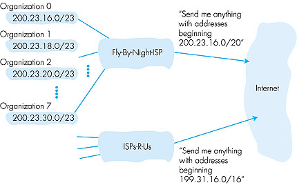
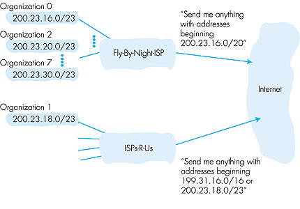
ISP's block 11001000 00010111 00010000 00000000 200.23.16.0/20 Organization 0 11001000 00010111 00010000 00000000 200.23.16.0/23 Organization 1 11001000 00010111 00010010 00000000 200.23.18.0/23 Organization 2 11001000 00010111 00010100 00000000 200.23.20.0/23 ... Organization 7 11001000 00010111 00011110 00000000 200.23.30.0/23 Let's conclude our discussion of addressing by considering how an ISP itself gets a block of addresses. IP addresses are managed under the authority of The Internet Corporation for Assigned Names and Numbers (ICANN) [ICANN 2000] based on guidelines set forth in RFC 2050. The role of the nonprofit ICANN organization [NTIA 1998] is to allocate not only IP addresses, but also to manage the DNS root servers. It also has the very contentious job of assigning domain names and resolving domain name disputes. The actual assignment of addresses is now managed by regional Internet registries. As of mid-2000, there are three such regional registries: the American Registry for Internet Number (ARIN, which handles registrations for North and South America, as well as parts of Africa. ARIN has recently taken over a number of the functions previously provided by Network Solutions), the Reseaux IP Europeans (RIPE, which covers Europe and nearby countries), and the Asia Pacific Network Information Center (APNIC). Before leaving our discussion of addressing, we want to mention that mobile hosts may change the network to which they are attached, either dynamically while in motion or on a longer time scale. Because routing is to a network first, and then to a host within the network, this means that the mobile host's IP address must change when the host changes networks. Techniques for handling such issues are now under development within the IETF and the research community [RFC 2002; RFC 2131].
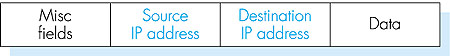
4.4.2: Transporting a Datagram from Source to Destination: Addressing and RoutingNow that we have defined interfaces and networks and have a basic understanding of IP addressing, we take a step back and examine how hosts and routers transport an IP datagram from source to destination. To this end, a high-level view of an IP datagram is shown in Figure 4.21. Every IP datagram has a source address field and a destination address field. The source host fills a datagram's source address field with its own 32-bit IP address. It fills the destination address field with the 32-bit IP address of the final destination host to which the datagram is being sent. The data field of the datagram is typically filled with a TCP or UDP segment. We'll discuss the remaining IP datagram fields a little later in this section.
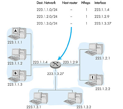
Once the source host creates the IP datagram, how does the network layer transport the datagram from the source host to the destination host? The answer to this question depends on whether the source and destination reside on the same network (where the term "network" is used here in the precise, addressing sense discussed in Section 4.4.1). Let's consider this question in the context of the network shown in Figure 4.22. First suppose host A wants to send an IP datagram to host B, which resides on the same network, 223.1.1.0/24, as A. This is accomplished as follows. IP in host A first consults its internal routing table, shown in Figure 4.22, and finds an entry, 223.1.1.0/24, whose network address matches the leading bits in the IP address of host B. The routing table shows that the number of hops to network 223.1.1.0 is 1, indicating that B is on the very same network to which A itself is attached. Host A thus knows that destination host B can be reached directly via A's outgoing interface, without the need for any intervening routers. Host A then passes the IP datagram to the link-layer protocol for the interface, which then has the responsibility of transporting the datagram to host B. (We'll study how the link layer transports a datagram between two interfaces on the same network in Chapter 5.)
Let's next consider the more interesting case that host A wants to send a datagram to another host, say E, that is on a different network. Host A again consults its routing table and finds an entry, 223.1.2.0/24, whose network address matches the leading bits in the IP address of host E. Because the number of hops to the destination is 2, host A knows that the destination is on another network and thus an intervening router will necessarily be involved. The routing table also tells host A that in order to get the datagram to host E, host A should first send the datagram to IP address 223.1.1.4, the router interface to which A's own interface is directly connected. IP in host A then passes the datagram down to the link layer and indicates to the link layer that it should send the datagram to IP address 223.1.1.4. It's important to note here that although the datagram is being sent (via the link layer) to the router's interface, the destination address of the datagram remains that of the ultimate destination (host E,) not that of the intermediate router interface. The datagram is now in the router, and it is the job of the router to move the datagram toward its ultimate destination. As shown in Figure 4.23, the router consults it own routing table and finds an entry, 223.1.2.0/24, whose network address matches the leading bits in the IP address of host E. The routing table indicates that the datagram should be forwarded on router interface 223.1.2.9. Since the number of hops to the destination is 1, the router knows that destination host E is on the same network as its own interface, 223.1.2.9. The router thus moves the datagram to this interface, which then transmits the datagram to host E.
In Figure 4.23, note that the entries in the "next router" column are all empty since each of the networks (223.1.1.0/24., 223.1.2.0/24, and 223.1.3.0/24) is directly attached to the router. In this case, there is no need to go through an intermediate router to get to a destination host. However, if host A and host E were separated by two routers, then within the routing table of the first router along the path from A to B, the appropriate row would indicate 2 hops to the destination and would specify the IP address of the second router along the path. The first router would then forward the datagram to the second router, using the link-layer protocol that connects the two routers. The second router would then forward the datagram to the destination host, using the link-layer protocol that connects the second router to the destination host. You may recall from Chapter 1 that we said that routing a datagram in the Internet is similar to a person driving a car and asking gas station attendants at each intersection along the way how to get to the ultimate destination. It should now be clear why this an appropriate analogy for routing in the Internet. As a datagram travels from source to destination, it visits a series of routers. At each router in the series, it stops and asks the router how to get to its ultimate destination. Unless the router is on the same network as the ultimate destination, the routing table essentially says to the datagram: "I don't know exactly how to get to the ultimate destination, but I do know that the ultimate destination is in the direction of the link (analogous to a road) connected to one of my interfaces." The datagram then sets out on the link connected to this interface, arrives at a new router, and again asks for new directions. From this discussion we see that the routing tables in the routers play a central role in routing datagrams through the Internet. But how are these routing tables configured and maintained for large networks with multiple paths between sources and destinations (such as in the Internet)? Clearly, these routing tables should be configured so that the datagrams follow "good" routes from source to destination. As you probably guessed, routing algorithms--like those studied in Section 4.2--have the job of configuring and maintaining the routing tables. We will discuss the Internet's routing algorithms in Section 4.5. But before moving on to routing algorithms, we cover three more important topics for the IP protocol, namely, the datagram format, datagram fragmentation, and the Internet Control Message Protocol (ICMP). 4.4.3: Datagram FormatThe IPv4 datagram format is shown in Figure 4.24.
The key fields in the IPv4 datagram are the following:
4.4.4: IP Fragmentation and ReassemblyWe will see in Chapter 5 that not all link-layer protocols can carry packets of the same size. Some protocols can carry "big" packets, whereas other protocols can only carry "little" packets. For example, Ethernet packets can carry no more than 1,500 bytes of data, whereas packets for many wide-area links can carry no more than 576 bytes. The maximum amount of data that a link-layer packet can carry is called the MTU (maximum transfer unit). Because each IP datagram is encapsulated within the link-layer packet for transport from one router to the next router, the MTU of the link-layer protocol places a hard limit on the length of an IP datagram. Having a hard limit on the size of an IP datagram is not much of a problem. What is a problem is that each of the links along the route between sender and destination can use different link-layer protocols, and each of these protocols can have different MTUs.To understand the problem better, imagine that you are a router that interconnects several links, each running different link-layer protocols with different MTUs. Suppose you receive an IP datagram from one link, you check your routing table to determine the outgoing link, and this outgoing link has an MTU that is smaller than the length of the IP datagram. Time to panic--how are you going to squeeze this oversized IP packet into the payload field of the link-layer packet? The solution to this problem is to "fragment" the data in the IP datagram among two or more smaller IP datagrams, and then send these smaller datagrams over the outgoing link. Each of these smaller datagrams is referred to as a fragment. Fragments need to be reassembled before they reach the transport layer at the destination. Indeed, both TCP and UDP are expecting to receive complete, unfragmented segments from the network layer. The designers of IPv4 felt that reassembling (and possibly refragmenting) datagrams in the routers would introduce significant complication into the protocol and put a damper on router performance. (If you were a router, would you want to be reassembling fragments on top of everything else you have to do?) Sticking to the principle of keeping the network layer simple, the designers of IPv4 decided to put the job of datagram reassembly in the end systems rather than in network routers. When a destination host receives a series of datagrams from the same source, it needs to determine if any of these datagrams are fragments of some original larger datagram. If it does determine that some datagrams are fragments, it must further determine when it has received the last fragment and how the fragments it has received should be pieced back together to form the original datagram. To allow the destination host to perform these reassembly tasks, the designers of IP (version 4) put identification, flag, and fragmentation fields in the IP datagram. When a datagram is created, the sending host stamps the datagram with an identification number as well as a source and destination address. The sending host increments the identification number for each datagram it sends. When a router needs to fragment a datagram, each resulting datagram (that is, "fragment") is stamped with the source address, destination address, and identification number of the original datagram. When the destination receives a series of datagrams from the same sending host, it can examine the identification numbers of the datagrams to determine which of the datagrams are actually fragments of the same, larger datagram. Because IP is an unreliable service, one or more of the fragments may never arrive at the destination. For this reason, in order for the destination host to be absolutely sure it has received the last fragment of the original datagram, the last fragment has a flag bit set to 0 whereas all the other fragments have this flag bit set to 1. Also, in order for the destination host to determine if a fragment is missing (and also to be able to reassemble the fragments in their proper order), the offset field is used to specify where the fragment fits within the original IP datagram. Figure 4.25 illustrates an example. A datagram of 4,000 bytes arrives at a router, and must be forwarded to a link with an MTU of 1,500 bytes. This implies that the 3,980 data bytes in the original datagram must be allocated to three separate fragments (each of which are also IP datagrams). Suppose that the original datagram is stamped with an identification number of 777. The characteristics of the three fragments are shown in Table 4.3.
Table 4.3: IP Fragments
The payload of the datagram is only passed to the transport layer at the destination once the IP layer has fully reconstructed the original IP datagram. If one or more of the fragments does not arrive to the destination, the datagram is discarded and not passed to the transport layer. But, as we learned in the previous chapter, if TCP is being used at the transport layer, then TCP will recover from this loss by having the source retransmit the data in the original datagram. Fragmentation and reassembly puts an additional burden on Internet routers (the additional effort to create fragments out of a datagram) and on the destination hosts (the additional effort to reassemble fragments). For this reason it is desirable to keep fragmentation to a minimum. This is often done by limiting the TCP and UDP segments to a relatively small size, so that fragmentation of the corresponding datagrams is unlikely. Because all data-link protocols supported by IP are supposed to have MTUs of at least 576 bytes, fragmentation can be entirely eliminated by using an MSS of 536 bytes, 20 bytes of TCP segment header and 20 bytes of IP datagram header. This is why most TCP segments for bulk data transfer (such as with HTTP) are 512-536 bytes long. (You may have noticed while surfing the Web that 500 or so bytes of data often arrive at a time.) Following this section, we provide a Java applet that generates fragments. You provide the incoming datagram size, the MTU, and the incoming datagram identification. It automatically generates the fragments for you. Click here to open it in a new window, or select it from the menu bar at the left. 4.4.5: ICMP: Internet Control Message ProtocolWe conclude this section with a discussion of the Internet Control Message Protocol, ICMP, which is used by hosts, routers, and gateways to communicate network layer information to each other. ICMP is specified in RFC 792. The most typical use of ICMP is for error reporting. For example, when running a Telnet, FTP, or HTTP session, you may have encountered an error message such as "Destination network unreachable." This message had its origins in ICMP. At some point, an IP router was unable to find a path to the host specified in your Telnet, FTP, or HTTP application. That router created and sent a type-3 ICMP message to your host indicating the error. Your host received the ICMP message and returned the error code to the TCP code that was attempting to connect to the remote host. TCP, in turn, returned the error code to your application.ICMP is often considered part of IP, but architecturally lies just above IP, as ICMP messages are carried inside IP packets. That is, ICMP messages are carried as IP payload, just as TCP or UDP segments are carried as IP payload. Similarly, when a host receives an IP packet with ICMP specified as the upper-layer protocol, it demultiplexes the packet to ICMP, just as it would demultiplex a packet to TCP or UDP. ICMP messages have a type and a code field, and also contain the first eight bytes of the IP datagram that caused the ICMP message to be generated in the first place (so that the sender can determine the packet that caused the error). Selected ICMP messages are shown below in Figure 4.26. Note that ICMP messages are used not only for signaling error conditions. The well-known ping program sends an ICMP type 8 code 0 message to the specified host. The destination host, seeing the echo request, sends back a type 0 code 0 ICMP echo reply. Another interesting ICMP message is the source quench message. This message is seldom used in practice. Its original purpose was to perform congestion control--to allow a congested router to send an ICMP source quench message to a host to force that host to reduce its transmission rate. We have seen in Chapter 3 that TCP has its own congestion-control mechanism that operates at the transport layer, without the use of network-layer feedback such as the ICMP source quench message.
Figure 4.26:
IP Fragmentation
In Chapter 1 we introduced the Traceroute program, which enabled you to trace the route from a few given hosts to any host in the world. Interestingly, Traceroute also uses ICMP messages. To determine the names and addresses of the routers between source and destination, Traceroute in the source sends a series of ordinary IP datagrams to the destination. The first of these datagrams has a TTL of 1, the second of 2, the third of 3, etc. The source also starts timers for each of the datagrams. When the nth datagram arrives at the nth router, the nth router observes that the TTL of the datagram has just expired. According to the rules of the IP protocol, the router discards the datagram and sends an ICMP warning message to the source (type 11 code 0). This warning message includes the name of the router and its IP address. When this ICMP message arrives at the source, the source obtains the round-trip time from the timer and the name and IP address of the nth router from the ICMP message. Now that you understand how Traceroute works, you may want to go back and play with it some more. |