4.5: Routing in the Internet
| Having studied
Internet addressing and the IP protocol, we now turn our attention to the
Internet's routing protocols; their job is to determine the path taken
by a datagram between source and destination. We'll see that the Internet's
routing protocols embody many of the principles we learned earlier in this
chapter. The link state and distance vector approaches studied in Section
4.2, and the notion of an autonomous system (AS) considered in Section
4.3 are all central to how routing is done in today's Internet.
Informally, we know that the Internet is a loose confederation of interconnected "networks" of local, regional, national, and international ISPs. We'll now need to make this understanding a bit more precise, given that we've seen that the notion of "network" has a very precise meaning in terms of IP addressing. Recall from Section 4.3 that a collection of routers that are under the same administrative and technical control, and that all run the same routing protocol amongst themselves, is known as an autonomous system (AS). Each AS, in turn, is typically comprised of multiple networks (where we use the term "network" in the precise, addressing sense of Section 4.4). The most important distinction to be made among Internet routing protocols is whether they are used to route datagrams within a single AS, or among multiple ASs. We consider the first class of protocols, known as intra-autonomous system routing protocols, in Section 4.5.1. We consider the second class of protocols, inter-autonomous system routing protocols, in Section 4.5.2. 4.5.1: Intra-Autonomous-System Routing in the InternetAn intra-AS routing protocol is used to configure and maintain the routing tables within an autonomous system (AS). Intra-AS routing protocols are also known as interior gateway protocols. Historically, three routing protocols have been used extensively for routing within an autonomous system in the Internet: RIP (the Routing Information Protocol), OSPF (Open Shortest Path First), and EIGRP (Cisco's propriety Enhanced Interior Gateway Routing Protocol).RIP: Routing Information Protocol The Routing Information Protocol (RIP) was one of the earliest intra-AS Internet routing protocols and is still in widespread use today. It traces its origins and its name to the Xerox Network Systems (XNS) architecture. The widespread deployment of RIP was due in great part to its inclusion in 1982 of the Berkeley Software Distribution (BSD) version of UNIX supporting TCP/IP. RIP version 1 is defined in RFC 1058, with a backwards compatible version 2 defined in RFC 1723. RIP is a distance vector protocol that operates in a manner very close to the idealized protocol we examined in Section 4.2.3. The version of RIP specified in RFC 1058 uses hop count as a cost metric; that is, each link has a cost of 1. The maximum cost of a path is limited to 15, thus limiting the use of RIP to autonomous systems that are less than 15 hops in diameter. Recall that in distance vector protocols, neighboring routers exchange routing information with each other. In RIP, routing tables are exchanged between neighbors approximately every 30 seconds using a so-called RIP response message. The response message sent by a router or host contains the sender's routing table entries for up to 25 destination networks within the AS. Response messages are also known as RIP advertisements. Let's take a look at a simple example of how RIP advertisements work. Consider the portion of an AS shown in Figure 4.27. In this figure, lines connecting the routers denote networks. Only selected routers (A,B,C, and D) and networks (w,x,y,z) are labeled for visual convenience. Dotted lines indicate that the AS continues on, and thus this autonomous system has many more routers and links than are shown in the Figure 4.27.
Now suppose that the routing table for router D is as shown in Figure 4.28. Note that the routing table has three columns. The first column is for the destination network, the second column indicates the identity of the next router along the shortest path to the destination network, and the third column indicates the number of hops (that is, the number of networks that have to be traversed, including the destination network) to get to the destination network along the shortest path. For this example, the table indicates that to send a datagram from router D to destination network w, the datagram should be first sent to neighboring router A; the table also indicates that destination network w is two hops away along the shortest path. Similarly, the table indicates that network z is seven hops away via router B. In principle, a routing table will have one row for each network in the AS, although RIP version 2 allows routes to networks to be aggregated using the route aggregation techniques similar to those we examined in Section 4.4.1. The routing table will also have at least one row for routing to networks that are outside of the AS. The table in Figure 4.28, and the subsequent tables to come, are thus only partially complete.
Figure 4.28: Routing table in router D before receiving advertisement from router A Now suppose that 30 seconds later, router D receives from router A the advertisement shown in Figure 4.29. Note that this advertisement is nothing other but the routing table in router A! This routing table says, in particular, that network z is only 4 hops away from router A. Router D, upon receiving this advertisement, merges the advertisement (Figure 4.29) with the "old" routing table (Figure 4.28). In particular, router D learns that there is now a path through router A to network z that is shorter than the path through router B.
Figure 4.29: Advertisement from router A Thus, router D updates its routing table to account for the "shorter" shortest path, as shown in Figure 4.30. How is it, you might ask, that the shortest path to network z has become shorter? Possibly, the decentralized distance vector algorithm was still in the process of converging (see Section 4.2), or perhaps new links and/or routers were added to the AS, thus changing the shortest paths in the network.
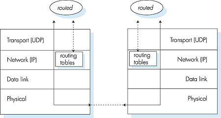
Figure 4.30: Routing table in router D after receiving advertisement from router A Let's next consider a few of the implementation aspects of RIP. Recall that RIP routers exchange advertisements approximately every 30 seconds. If a router does not hear from its neighbor at least once every 180 seconds, that neighbor is considered to be no longer reachable; that is, either the neighbor has died or the connecting link has gone down. When this happens, RIP modifies its local routing table and then propagates this information by sending advertisements to its neighboring routers (the ones that are still reachable). A router can also request information about its neighbor's cost to a given destination using RIP's request message. Routers send RIP request and response messages to each other over UDP using port number 520. The UDP packet is carried between routers in a standard IP packet. The fact that RIP uses a transport-layer protocol (UDP) on top of a network-layer protocol (IP) to implement network-layer functionality (a routing algorithm) may seem rather convoluted (it is!). Looking a little deeper at how RIP is implemented will clear this up. Figure 4.31 sketches how RIP is typically implemented in a UNIX system, for example, a UNIX workstation serving as a router. A process called routed (pronounced "route dee") executes the RIP protocol, that is, maintains the routing table and exchanges messages with routed processes running in neighboring routers. Because RIP is implemented as an application-layer process (albeit a very special one that is able to manipulate the routing tables within the UNIX kernel), it can send and receive messages over a standard socket and use a standard transport protocol. Thus, RIP is an application-layer protocol (see Chapter 2) running over UDP.
Finally, let us take a quick look at a RIP routing table. The RIP routing table in Figure 4.32 is taken from a UNIX router giroflee.eurecom.fr. If you give a netstat -rn command on a UNIX system, you can view the routing table for that host or router. Performing a netstat command on giroflee.eurecom.fr yields the routing table in Figure 4.32. Destination Gateway Flags Ref Use Interface ------------ -------------- ----- ---- ------ -------- 127.0.0.1 127.0.0.1 UH 0 26492 1o0 192.168.2. 192.168.2.5 U 2 13 fa0 193.55.114. 193.55.114.6 U 3 58503 le0 192.168.3. 192.168.3.5 U 2 25 qaa0 224.0.0.0 193.55.114.6 U 3 0 le0 default 193.55.114.129 UG 0 143454Figure 4.32: RIP routing table from giroflee.eurecom.fr The router giroflee is connected to three networks. The second, third, and fourth rows in the table tell us that these three networks are attached to giroflee via giroflee's network interfaces fa0, le0 and qaa0. These giroflee interfaces have IP addresses 192.168.2.5, 193.55.114.6, and 192.168.3.5, respectively. To transmit a packet to any host belonging to one of these three networks, giroflee will simply send the outgoing IP datagram over the appropriate interface. Of particular interest to us is the default route. Any IP datagram that is not destined for one of the networks explicitly listed in the routing table will be forwarded to the router with IP address 193.55.114.129; this router is reached by sending the datagram over the default network interface. The first entry in the routing table is the so-called loopback interface. When IP sends a datagram to the loopback interface, the packet is simply returned back to IP; this is useful for debugging purposes. The address 224.0.0.0 is a special multicast (Class D) IP address. We will examine IP multicast in Section 4.8. OSPF: Open Shortest Path First Like RIP, Open Shortest Path First (OSPF) routing is used for intra-AS routing. The "Open" in OSPF indicates that the routing protocol specification is publicly available (for example, as opposed to Cisco's EIGRP protocol). The most recent version of OSPF, version 2, is defined in RFC 2178--a public document. OSPF was conceived as the successor to RIP and as such has a number of advanced features. At its heart, however, OSPF is a link-state protocol that uses flooding of link-state information and a Dijkstra least-cost-path algorithm. With OSPF, a router constructs a complete topological map (that is, a directed graph) of the entire autonomous system. The router then locally runs Dijkstra's shortest-path algorithm to determine a shortest-path tree to all networks with itself as the root node. The router's routing table is then obtained from this shortest-path tree. Individual link costs are configured by the network administrator. Let us now contrast and compare the advertisements sent by RIP and OSPF. With OSPF, a router periodically broadcasts routing information to all other routers in the autonomous system, not just to its neighboring routers. For an excellent treatment of link state broadcast algorithms, see [Perlman 1999]. This routing information sent by a router has one entry for each of the router's neighbors; the entry gives the distance (that is, link state) from the router to the neighbor. On the other hand, a RIP advertisement sent by a router contains information about all the networks in the autonomous system, although this information is only sent to its neighboring routers. In a sense, the advertising techniques of RIP and OSPF are duals of each other. Some of the advances embodied in OSPF include the following:
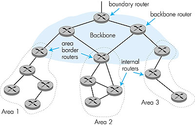
Within each area, one or more area border routers are responsible for routing packets outside the area. Exactly one OSPF area in the AS is configured to be the backbone area. The primary role of the backbone area is to route traffic between the other areas in the AS. The backbone always contains all area border routers in the AS and may contain nonborder routers as well. Inter-area routing within the AS requires that the packet be first routed to an area border router (intra-area routing), then routed through the backbone to the area border router that is in the destination area, and then routed to the final destination. A diagram of a hierarchically structured OSPF network is shown in Figure 4.33. We can identify four types of OSPF routers in Figure 4.33:
The Enhanced Interior Gateway Routing Protocol (EIGRP) [Cisco IGRP 1997] is a proprietary routing algorithm developed by Cisco Systems, Inc., as a successor for RIP. EIGRP is a distance vector protocol. Several cost metrics (including delay, bandwidth, reliability, and load) can be used in making routing decisions, with the weight given to each of the metrics being determined by the network administrator. This ability to use administrator-defined costs in making route selections is an important difference from RIP; we will see shortly that so-called policy-based inter-AS Internet routing protocols such as BGP also allow administratively defined routing decisions to be made. Other important differences from RIP include the use of a reliable transport protocol to communicate routing information, the use of update messages that are sent only when routing table costs change (rather than periodically), route aggregation, and the use of a distributed diffusing update routing algorithm [Garcia-Luna 1993] to quickly compute loop-free routing paths. 4.5.2: Inter-Autonomous System RoutingThe Border Gateway Protocol version 4, specified in RFC 1771 (see also RFC 1772; RFC 1773), is the de facto standard interdomain routing protocol in today's Internet. It is commonly referred to as BGP4 or simply as BGP. As an inter-autonomous system routing protocol, it provides for routing between autonomous systems (that is, administrative domains).While BGP has the same general flavor as the distance vector protocol that we studied in Section 4.2, it is more appropriately characterized as a path vector protocol. This is because BGP in a router does not propagate cost information (for example, number of hops to a destination), but instead propagates path information, such as the sequence of ASs on a route to a destination AS. We will examine the path information in detail shortly. We note though that although this information includes the names of the ASs on a route to the destination, it does not contain cost information. Nor does BGP specify how a specific route to a particular destination should be chosen among the routes that have been advertised. That decision is a policy decision that is left up to the domain's administrator. Each domain can thus choose its routes according to whatever criteria it chooses (and need not even inform its neighbors of its policy!)--allowing a significant degree of autonomy in route selection. In essence, BGP provides the mechanisms to distribute path information among the interconnected autonomous systems, but leaves the policy for making the actual route selections up to the network administrator. Let's begin with a grossly simplified description of how BGP works. This will help us see the forest through the trees. As discussed in Section 4.3, as far as BGP is concerned, the whole Internet is a graph of ASs, and each AS is identified by an AS number. At any instant of time, a given AS X may, or may not, know of a path of ASs that lead to a given destination AS Z. As an example, suppose X has a path XY1Y2Y3Z from itself to Z listed in its BGP table. This means that X knows that it can send datagrams to Z through the ASs X, Y1, Y2, and Y3, Z. When X sends updates to its BGP neighbors (that is, the neighbors in the graph), X actually sends the entire path information, XY1Y2Y3Z, to its neighbors (as well as other paths to other ASs). If, for example, W is a neighbor of X, and W receives an advertisement that includes the path XY1Y2Y3Z, then W can list a new entry WXY1Y2Y3Z in its BGP table. However, we should keep in mind that W may decide to not create this new entry for one of several reasons. For example, W would not create this entry if W is equal to (say) Y2, thereby creating an undesirable loop in the routing; or if W already has a path to Z in its tables, and this existing path is preferable (with respect to the metric used by BGP at W) to WXY1Y2Y3Z; or, finally, if W has a policy decision to not forward datagrams through (say) Y2. In BGP jargon, the immediate neighbors in the graph of ASs are called peers. BGP information is propagated through the network by exchanges of BGP mes -sages between peers. The BGP protocol defines the four types of messages: OPEN, UPDATE, NOTIFICATION, and KEEPALIVE.
Very often an AS will have multiple gateway routers that provide connections to other ASs. Even though BGP is an inter-AS protocol, it can still be used inside an AS as a pipe to exchange BGP updates among gateway routers belonging to the same AS. BGP connections inside an AS are called Internal BGP (IBGP), whereas BGP connections between ASs are called External BGP (EBGP). As noted above, BGP is becoming the de facto standard for inter-AS routing for the public Internet. BGP is used, for example, at the major network access points (NAPs) where major Internet carriers connect to each other and exchange traffic. To see the contents of today's (less than four hours out of date) BGP routing table (large!) at one of the major NAPs in the U.S. (which include Chicago and San Francisco), see [IPMA 2000]. This completes our brief introduction of BGP. Although BGP is complex, it plays a central role in the Internet. We encourage readers to see the references [Stewart 1999; Labovitz 1997; Halabi 1997; Huitema 1995] to learn more about BGP.
|