4.6: What's Inside a Router?
| Our study of
the network layer so far has focused on network-layer service models, the
routing algorithms that control the routes taken by packets through the
network, and the protocols that embody these routing algorithms. These
topics, however, are only part (albeit important ones) of what goes on
in the network layer. We have yet to consider the switching function
of a router--the actual transfer of datagrams from a router's incoming
links to the appropriate outgoing links. Studying just the control and
service aspects of the network layer is like studying a company and considering
only its management (which controls the company but typically performs
very little of the actual "grunt" work that makes a company run!) and its
public relations ("Our product will provide this wonderful service to you!").
To fully appreciate what really goes on within a company, one needs to
consider the workers. In the network layer, the real work (that is, the
reason the network layer exists in the first place) is the forwarding of
datagrams. A key component in this forwarding process is the transfer of
a datagram from a router's incoming link to an outgoing link. In this section,
we study how this is accomplished. Our coverage here is necessarily brief,
as an entire course would be needed to cover router design in depth. Consequently,
we'll make a special effort in this section to provide pointers to material
that covers this topic in more depth.
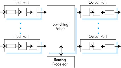
A high-level view of a generic router architecture is shown in Figure 4.34. Four components of a router can be identified:
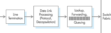
4.6.1: Input PortsA more detailed view of input port functionality is given in Figure 4.35. As discussed above, the input port's line termination function and data link processing implement the physical and data link layers associated with an individual input link to the router. The lookup/forwarding function of the input port is central to the switching function of the router. In many routers, it is here that the router determines the output port to which an arriving packet will be forwarded via the switching fabric. The choice of the output port is made using the information contained in the routing table. Although the routing table is computed by the routing processor, a shadow copy of the routing table is typically stored at each input port and updated, as needed, by the routing processor. With local copies of the routing table, the switching decision can be made locally, at each input port, without invoking the centralized routing processor. Such decen tralized switching avoids creating a forwarding bottle neck at a single point within the router.
In routers with limited processing capabilities at the input port, the input port may simply forward the packet to the centralized routing processor, which will then perform the routing table lookup and forward the packet to the appropriate output port. This is the approach taken when a workstation or server serves as a router; here, the routing processor is really just the workstation's CPU and the input port is really just a network interface card (for example, an Ethernet card). Given the existence of a routing table, the routing table lookup is concep tually simple--we just search through the routing table, looking for a destination entry that best matches the destination network address of the packet, or a default route if the destination entry is missing. (Recall from our discussion in Section 4.4.1 that the best match is the routing table entry with the longest network prefix that matches the packet's des tination address.) In practice, however, life is not so simple. Perhaps the most important complicating factor is that backbone routers must operate at high speeds, being capable of performing millions of lookups per second. Indeed, it is desirable for the input port processing to be able to proceed at line speed, that is, that a lookup can be done in less than the amount of time needed to receive a packet at the input port. In this case, input processing of a received packet can be completed before the next receive operation is complete. To get an idea of the performance requirements for a lookup, consider that a so-called OC48 link runs at 2.5 Gbps. With 256-byte-long packets, this implies a lookup speed of approximately a million lookups per second. Given the need to operate at today's high-link speeds, a linear search through a large routing table is impossible. A more reasonable technique is to store the routing table entries in a tree data structure. Each level in the tree can be thought of as corresponding to a bit in the destination address. To look up an address, one simply starts at the root node of the tree. If the first address bit is a zero, then the left subtree will contain the routing table entry for a destination address; otherwise it will be in the right subtree. The appropriate subtree is then traversed using the remaining address bits--if the next address bit is a zero, the left subtree of the initial subtree is chosen; otherwise, the right subtree of the initial subtree is chosen. In this manner, one can look up the routing table entry in N steps, where N is the number of bits in the address. (The reader will note that this is essentially a binary search through an address space of size 2N.) Refinements of this approach are discussed in [Doeringer 1996]. An improvement over binary search techniques is described in [Srinivasan 1999]. But even with N = 32 (for example, a 32-bit IP address) steps, the lookup speed via binary search is not fast enough for today's backbone routing requirements. For example, assuming a memory access at each step, less than a million address lookups/sec could be performed with 40 ns memory access times. Several techniques have thus been explored to increase lookup speeds. Content addressable memories (CAMs) allow a 32-bit IP address to be presented to the CAM, which then returns the content of the routing table entry for that address in essentially constant time. The Cisco 8500 series router [Cisco 8500 1999] has a 64K CAM for each input port. Another technique for speeding lookup is to keep recently accessed routing table entries in a cache [Feldmeier 1988]. Here, the potential concern is the size of the cache. Measurements in [Thomson 1997] suggest that even for an OC-3 speed link, approximately 256,000 source-destination pairs might be seen in one minute in a backbone router. Most recently, even faster data structures, which allow routing table entries to be located in log(N) steps [Waldvogel 1997], or which compress routing tables in novel ways [Brodnik 1997], have been proposed. A hardware-based approach to lookup that is optimized for the common case that the address being looked up has 24 or fewer significant bits is discussed in [Gupta 1998]. Once the output port for a packet has been determined via the lookup, the packet can be forwarded into the switching fabric. However, as we'll see below, a packet may be temporarily blocked from entering the switching fabric (due to the fact that packets from other input ports are currently using the fabric). A blocked packet must thus be queued at the input port and then scheduled to cross the switching fabric at a later point in time. We'll take a closer look at the blocking, queuing, and scheduling of packets (at both input ports and output ports) within a router in Section 4.6.4.
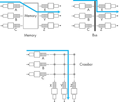
4.6.2: Switching FabricsThe switching fabric is at the very heart of a router. It is through this switching fabric that the packets are actually moved from an input port to an output port. Switching can be accomplished in a number of ways, as indicated in Figure 4.36.
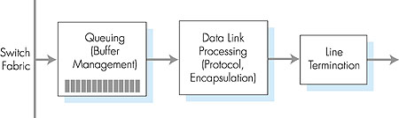
4.6.3: Output PortsOutput port processing, shown in Figure 4.37, takes the datagrams that have been stored in the output port's memory and transmits them over the outgoing link. The data-link protocol processing and line termination are the send-side link- and physical-layer functionality that interact with the input port on the other end of the outgoing link, as discussed above in Section 4.6.1. The queuing and buffer management functionality are needed when the switch fabric delivers packets to the output port at a rate that exceeds the output link rate; we'll cover output port queuing below.
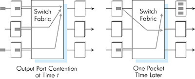
4.6.4: Where Does Queuing Occur?If we look at the input and output port functionality and the configurations shown in Figure 4.36, it is evident that packet queues can form at both the input ports and the output ports. It is important to consider these queues in a bit more detail, since as these queues grow large, the router's buffer space will eventually be exhausted and packet loss will occur. Recall that in our earlier discussions, we said rather vaguely that packets were lost "within the network" or "dropped at a router." It is here, at these queues within a router, where such packets are dropped and lost. The actual location of packet loss (either at the input port queues or the output port queues) will depend on the traffic load, the relative speed of the switching fabric and the line speed, as discussed below.Suppose that the input line speeds and output line speeds are all identical, and that there are n input ports and n output ports. If the switching fabric speed is at least n times as fast as the input line speed, then no queuing can occur at the input ports. This is because even in the worst case that all n input lines are receiving packets, the switch will be able to transfer n packets from input port to output port in the time it takes each of the n input ports to (simultaneously) receive a single packet. But what can happen at the output ports? Let us suppose still that the switching fabric is at least n times as fast as the line speeds. In the worst case, the packets arriving at each of the n input ports will be destined to the same output port. In this case, in the time it takes to receive (or send) a single packet, n packets will arrive at this output port. Since the output port can only transmit a single packet in a unit of time (the packet transmission time), the n arriving packets will have to queue (wait) for transmission over the outgoing link. n more packets can then possibly arrive in the time it takes to transmit just one of the n packets that had previously been queued. And so on. Eventually, the number of queued packets can grow large enough to exhaust the memory space at the output port, in which case packets are dropped. Output port queuing is illustrated in Figure 4.38. At time t, a packet has arrived at each of the incoming input ports, each destined for the uppermost outgoing port. Assuming identical line speeds and a switch operating at three times the line speed, one time unit later (that is, in the time needed to receive or send a packet), all three original packets have been transferred to the outgoing port and are queued awaiting transmission. In the next time unit, one of these three packets will have been transmitted over the outgoing link. In our example, two new packets have arrived at the incoming side of the switch; one of these packets is destined for this uppermost output port.
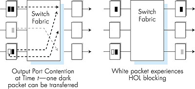
A consequence of output port queuing is that a packet scheduler at the output port must choose one packet among those queued for transmission. This selection might be done on a simple basis such as first-come-first-served (FCFS) scheduling, or a more sophisticated scheduling discipline such as weighted fair queuing (WFQ), which shares the outgoing link "fairly" among the different end-to-end connections that have packets queued for transmission. Packet scheduling plays a crucial role in providing quality-of-service guarantees. We will cover this topic extensively in Section 6.6. A discussion of output port packet scheduling disciplines used in today's routers is [Cisco Queue 1995]. If the switch fabric is not fast enough (relative to the input line speeds) to transfer all arriving packets through the fabric without delay, then packet queuing will also occur at the input ports, as packets must join input port queues to wait their turn to be transferred through the switching fabric to the output port. To illustrate an important consequence of this queuing, consider a crossbar switching fabric and suppose that (1) all link speeds are identical, (2) that one packet can be transferred from any one input port to a given output port in the same amount of time it takes for a packet to be received on an input link, and (3) packets are moved from a given input queue to their desired output queue in a FCFS manner. Multiple packets can be transferred in parallel, as long as their output ports are different. However, if two packets at the front of two input queues are destined to the same output queue, then one of the packets will be blocked and must wait at the input queue--the switching fabric can only transfer one packet to a given output port at a time. Figure 4.39 shows an example where two packets (shaded black) at the front of their input queues are destined for the same upper-right output port. Suppose that the switch fabric chooses to transfer the packet from the front of the upper-left queue. In this case, the black packet in the lower-left queue must wait. But not only must this black packet wait, but so too must the white packet that is queued behind that packet in the lower-left queue, even though there is no contention for the middle-right output port (the destination for the white packet). This phenomenon is known as head-of-the-line (HOL) blocking in an input-queued switch--a queued packet in an input queue must wait for transfer through the fabric (even though its output port is free) because it is blocked by another packet at the head of the line. [Karol 1987] shows that due to HOL blocking, the input queue will grow to unbounded length (informally, this is equivalent to saying that significant packet loss will occur) under certain assumptions as soon as the packet arrival rate on the input links reaches only 58 percent of their capacity. A number of solutions to HOL blocking are discussed in [McKeown 1997b].
|