5.4: LAN Addresses and ARP
As we learned
in the previous section, nodes in LANs send frames to each other over a
broadcast channel. This means that when a node in a LAN transmits a frame,
every other node connected to the LAN receives the frame. But usually,
a node in the LAN doesn't want to send a frame to all of the other
LAN nodes but instead wants to send to some particular LAN node.
To provide this functionality, the nodes on the LAN must be able to address
each other when sending frames, that is, the nodes need LAN addresses and
the link-layer frame needs a field to contain such a destination address.
In this manner, when a node receives a frame, it can determine whether
the frame was intended for it or for some other node in the LAN:
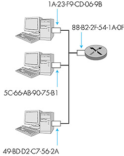
5.4.1: LAN AddressesIn truth, it is not a node that has a LAN address but instead a node's adapter that has a LAN address. This is illustrated in Figure 5.19. A LAN address is also variously called a physical address, an Ethernet address, or a MAC (media access control) address. For most LANs (including Ethernet and token-passing LANs), the LAN address is six-bytes long, giving 248 possible LAN addresses. These six-byte addresses are typically expressed in hexadecimal notation, with each byte of the address expressed as a pair of hexadecimal numbers. An adapter's LAN address is permanent--when an adapter is manufactured, a LAN address is burned into the adapter's ROM.
One interesting property of LAN addresses is that no two adapters have the same address. This might seem surprising given that adapters are manufactured in many different countries by many different companies. How does a company manufacturing adapters in Taiwan make sure that it is using different addresses from a company manufacturing adapters in Belgium? The answer is that IEEE manages the physical address space. In particular, when a company wants to manufacture adapters, it purchases a chunk of the address space consisting of 224 addresses for a nominal fee. IEEE allocates the chunk of 224 addresses by fixing the first 24 bits of a physical address and letting the company create unique combinations of the last 24 bits for each adapter. An adapter's LAN address has a flat structure (as opposed to a hierarchical structure), and doesn't change no matter where the adapter goes. A portable computer with an Ethernet card always has the same LAN address, no matter where the portable goes. Recall that, in contrast, an IP address has a hierarchical structure (that is, a network part and a host part), and a node's IP address needs to be changed when the host moves. An adapter's LAN address is analogous to a person's social security number, which also has a flat addressing structure and which doesn't change no matter where the person goes. An IP address is analogous to a person's postal address, which is hierarchical and which needs to be changed whenever a person moves. As we described at the beginning of this section, when an adapter wants to send a frame to some destination adapter on the same LAN, the sending adapter inserts the destination's LAN address into the frame. When the destination adapter receives the frame, it extracts the enclosed datagram and passes the datagram up the protocol stack. All the other adapters on the LAN also receive the frame. However, these other adapters discard the frame without passing the network-layer datagram up the protocol stack. Thus, these other adapters do not have to interrupt their hosting node when they receive datagrams destined to other nodes. However, sometimes a sending adapter does want all the other adapters on the LAN to receive and process the frame it is about to send. In this case, the sending adapter inserts a special LAN broadcast address into the destination address field of the frame. For LANs that use six-byte addresses (such as Ethernet and token-passing LANs), the broadcast address is a string of 48 consecutive 1s (that is, FF-FF-FF-FF-FF-FF in hexadecimal notation).
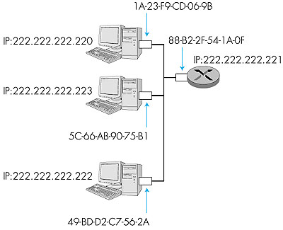
5.4.2: Address Resolution ProtocolBecause there are both network-layer addresses (for example, Internet IP addresses) and link-layer addresses (that is, LAN addresses), there is a need to translate between them. For the Internet, this is the job of the address resolution protocol (ARP) [RFC 826]. Every Internet host and router on a LAN has an ARP module.To motivate ARP, consider the network shown in Figure 5.20. In this simple example, each node has a single IP address and each node's adapter has a LAN address. As usual, IP addresses are shown in dotted-decimal notation and LAN addresses are shown in hexadecimal notation. Now suppose that the node with IP address 222.222.222.220 wants to send an IP datagram to node 222.222.222.222. To accomplish this task, the sending node must give its adapter not only the IP datagram but also the LAN address for node 222.222.222.222. When passed the IP datagram and the LAN address, the sending node's adapter will construct a data-link layer frame containing the receiving node's LAN address and send the frame into the LAN. But how does the sending node determine the LAN address for the node with IP address 222.222.222.222? It does this by providing its ARP module with the IP address 222.222.222.222. ARP then responds with the corresponding LAN address, namely, 49-BD-D2-C7-56-2A.
So we see that ARP resolves an IP address to a LAN address. In many ways it is analogous to DNS (studied in Section 2.5), which resolves hostnames to IP addresses. However, one important difference between the two resolvers is that DNS resolves hostnames for hosts anywhere in the Internet, whereas ARP only resolves IP addresses for nodes on the same LAN. If a node in California were to try to use ARP to resolve the IP address for a node in Mississippi, ARP would return with an error. Now that we have explained what ARP does, let's look at how it works. The ARP module in each node has a table in its RAM called an ARP table. This table contains the mappings of IP addresses to LAN addresses. Figure 5.21 shows what an ARP table in node 222.222.222.220 might look like. For each address mapping the table also contains a time-to-live (TTL) entry, which indicates when the entry will be deleted from the table. Note that the table does not necessarily contain an entry for every node on the LAN; some nodes may have had entries that expired over time, whereas other nodes may have never been entered into the table. A typical expiration time for an entry is 20 minutes from when an entry is placed in an ARP table.
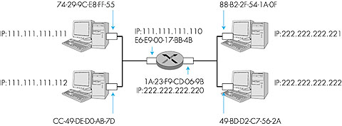
Figure 5.21: A possible ARP table in node 222.222.222.220 Now suppose that node 222.222.222.220 wants to send a datagram that is IP-addressed to another node on that LAN. The sending node needs to obtain the LAN address of the destination node, given the IP address of that node. This task is easy if the sending node's ARP table has an entry for the destination node. But what if the ARP table doesn't currently have an entry for the destination node? In particular, suppose node 222.222.222.220 wants to send a datagram to node 222.222.222.222. In this case, the sending node uses the ARP protocol to resolve the address. First, the sending node constructs a special packet called an ARP packet. An ARP packet has several fields, including the sending and receiving IP and LAN addresses. Both ARP query and response packets have the same format. The purpose of the ARP query packet is to query all the other nodes on the LAN to determine the LAN address corresponding to the IP address that is being resolved. Returning to our example, node 222.222.222.220 passes an ARP query packet to the adapter along with an indication that the adapter should send the packet to the LAN broadcast address, namely, FF-FF-FF-FF-FF-FF. The adapter encapsulates the ARP packet in a data-link frame, uses the broadcast address for the frame's destination address, and transmits the frame into the LAN. Recalling our social security number/postal address analogy, note that an ARP query is equivalent to a person shouting out in a crowded room of cubicles in some company (say, AnyCorp): "What is the social security number of the person whose postal address is Cubicle 13, Room 112, AnyCorp, Palo Alto, CA?" The frame containing the ARP query is received by all the other adapters on the LAN, and (because of the broadcast address) each adapter passes the ARP packet within the frame up to its hosting node. Each node checks to see if its IP address matches the destination IP address in the ARP packet. The one node with a match sends back to the querying node a response ARP packet with the desired mapping. The querying node (222.222.222.220) can then update its ARP table and send its IP datagram. There are a couple of interesting things to note about the ARP protocol. First, the query ARP message is sent within a broadcast frame whereas the response ARP message is sent within a standard frame. Before reading on you should think about why this is so. Second, ARP is plug-and-play, that is, a node's ARP table gets built automatically--it doesn't have to be configured by a systems administrator. And if a node is disconnected from the LAN, its entry is eventually deleted from the table. Sending a datagram to a node off the LAN It should now be clear how ARP operates when a node wants to send a datagram to another node on the same LAN. But now let's look at the more complicated situation when a node on a LAN wants to send a network-layer datagram to a node off the LAN. Let us discuss this issue in the context of Figure 5.22, which shows a simple network consisting of two LANs interconnected by a router.
There are several interesting things to note about Figure 5.22. First, there are two types of nodes: hosts and routers. Each host has exactly one IP address and one adapter. But, as discussed in Section 4.4, a router has an IP address for each of its interfaces. Each router interface also has its own ARP module (in the router) and its own adapter. Because the router in Figure 5.22 has two interfaces, it has two IP addresses, two ARP modules, and two adapters. Of course, each adapter in the network has its own LAN address. Also note that all of the interfaces connected to LAN 1 have addresses of the form 111.111.111.xxx and all of the interfaces connected to LAN 2 have the form 222.222.222.xxx. Thus, in this example, the first three bytes of the IP address specifies the "network," whereas the last byte specifies the specific interface in the network. Now suppose that host 111.111.111.111 wants to send an IP datagram to host 222.222.222.222. The sending host passes the datagram to its adapter, as usual. But the sending host must also indicate to its adapter an appropriate destination LAN address. What LAN address should the adapter use? One might venture to guess that the appropriate LAN address is that of the adapter for host 222.222.222.222, namely, 49-BD-D2-C7-56-2A. This guess is, however, wrong. If the sending adapter were to use that LAN address, then none of the adapters on LAN 1 would bother to pass the IP datagram up to its network layer, since the frame's destination address would not match the LAN address of any adapter on LAN 1. The datagram would just die and go to datagram heaven. If we look carefully at Figure 5.22, we see that in order for a datagram to go from 111.111.111.111 to a node on LAN 2, the datagram must first be sent to the router interface 111.111.111.110. As discussed in Section 4.4, the routing table in host 111.111.111.111 would indicate that to reach host 222.222.222. 222, the datagram must first be sent to router interface 111.111.111.110. Thus, the appropriate LAN address for the frame is the address of the adapter for router interface 111.111.111.110, namely, E6-E9-00-17-BB-4B. How does the sending host acquire the LAN address of 111.111.111.110? By using ARP, of course! Once the sending adapter has this LAN address, it creates a frame and sends the frame into LAN 1. The router adapter on LAN 1 sees that the data-link frame is addressed to it, and therefore passes the frame to the network layer of the router. Hooray, the IP datagram has successfully been moved from source host to the router! But we are not done. We still have to move the datagram from the router to the destination! The router now has to determine the correct interface on which the datagram is to be forwarded. As discussed in Section 4.4, this is done by consulting a routing table in the router. The routing table tells the router that the datagram is to be forwarded via router interface 222.222.222.220. This interface then passes the datagram to its adapter, which encapsulates the datagram in a new frame and sends the frame into LAN 2. This time, the destination LAN address of the frame is indeed the LAN address of the ultimate destination. And how does the router obtain this destination LAN address? From ARP, of course! ARP for Ethernet is defined in RFC 826. A nice introduction to ARP is given in the TCP/IP tutorial, RFC 1180. We shall explore ARP in more detail in the homework problems. |