5.7: IEEE 802.11 LANs
In Section
5.5, we examined the dominant wired LAN protocol--Ethernet. In the previous
section we examined how LAN segments can be connected together via hubs,
bridges, and switches to form larger LANs. In this section we examine a
LAN standard (belonging to the same IEEE 802 family as Ethernet) that is
being increasingly deployed for untethered (wireless) LAN communication.
The IEEE 802.11 standard [Brenner
1997; Crow
1997; IEEE
802.11 1999] defines the physical layer and media access control (MAC)
layer for a wireless local area network. The standard defines three different
physical layers for the 802.11 wireless LAN, each operating in a different
frequency range and at rates of 1 Mbps and 2 Mbps. In this section we focus
on the architecture of 802.11 LANs and their media access protocols. We'll
see that although it belongs to the same standard family as Ethernet, it
has a significantly different architecture and media access protocol.
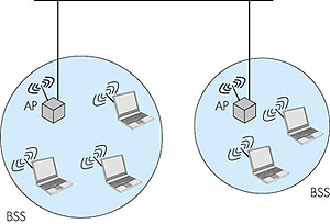
5.7.1: 802.11 LAN ArchitectureFigure 5.37 illustrates the principal components of the 802.11 wireless LAN architecture. The fundamental building block of the 802.11 architecture is the cell, known as the basic service set (BSS) in 802.11 parlance. A BSS typically contains one or more wireless stations and a central base station, known as an access point (AP) in 802.11 terminology. The wireless stations, which may be either fixed or mobile, and the central base station communicate among themselves using the IEEE 802.11 wireless MAC protocol. Multiple APs may be connected together (for example, using a wired Ethernet or another wireless channel) to form a so-called distribution system (DS). The DS appears to upper-level protocols (for example, IP) as a single 802 network, in much the same way that a bridged, wired 802.3 Ethernet network appears as a single 802 network to the upper-layer protocols.
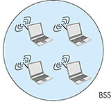
Figure 5.38 shows that IEEE 802.11 stations can also group themselves together to form an ad hoc network--a network with no central control and with no connections to the "outside world." Here, the network is formed "on the fly," simply because there happen to be mobile devices that have found themselves in proximity to each other, that have a need to communicate, and that find no pre-existing network infrastructure (for example, a pre-existing 802.11 BSS with an AP) in the location. An ad hoc network might be formed when people with laptops meet together (for example, in a conference room, a train, or a car) and want to exchange data in the absence of a centralized AP. There has been a tremendous recent increase in interest in ad hoc networking, as communicating portable devices continue to proliferate. Within the IETF, activity in ad hoc networking is centered around the mobile ad hoc networks (manet) working group [manet 2000].
5.7.2: 802.11 Media Access ProtocolsJust as in a wired 802.3 Ethernet network, stations in an IEEE 802.11 wireless LAN must coordinate their access and use of the shared communication media (in this case the radio frequency). Once again, this is the job of the Media Access Control (MAC) protocol. The IEEE 802.11 MAC protocol is a carrier-sense multiple access protocol with collision avoidance (CSMA/CA). Recall from our study of Ethernet in Section 5.5 that a CSMA protocol first senses the channel to determine if the channel is "busy" with the transmission of a frame from some other station. In the 802.11 specification, the physical layer monitors the energy level on the radio frequency to determine whether or not another station is transmitting and provides this carrier sensing information to the MAC protocol. If the channel is sensed idle for an amount of time equal to or greater than the Distributed Inter Frame Space (DIFS), a station is then allowed to transmit. As with any random access protocol, this frame will be successfully received at the destination station if no other station's transmission has interfered with the frame's transmission.When a receiving station has correctly and completely received a frame for which it was the addressed recipient, it waits a short period of time (known as the Short Inter Frame Spacing--SIFS) and then sends an explicit acknowledgment frame back to the sender. This data-link layer acknowledgment lets the sender know that the receiver has indeed correctly received the sender's data frame. We will see shortly that this explicit acknowledgment is needed because, unlike the case of wired Ethernet, a wireless sender cannot itself determine whether or not its frame transmission was successfully received at the destination. The transmission of a frame by a sending station and its subsequent acknowledgment by the destination station is shown in Figure 5.39.
Figure 5.39 illustrates the case when the sender senses the channel to be idle. What happens if the sender senses the channel busy? In this case, the station performs a backoff procedure that is similar to that of Ethernet. More specifically, a station that senses the channel busy will defer its access until the channel is later sensed idle. Once the channel is sensed idle for an amount of time equal to DIFS, the station then computes an additional random backoff time and counts down this time as the channel is sensed idle. When the random backoff timer reaches zero, the station transmits its frame. As in the case of Ethernet, the random backoff timer serves to avoid having multiple stations immediately begin transmission (and thus collide) after a DIFS idle period. As in the case of Ethernet, the interval over which the backoff timer randomizes is doubled each time a transmitted frame experiences a collision. We noted above that unlike the 802.3 Ethernet protocol, the wireless 802.11 MAC protocol does not implement collision detection. There are a couple of reasons for this:
Given these difficulties with detecting collisions at a wireless receiver, the designers of IEEE 802.11 developed an access protocol that aimed to avoid collisions (hence the name CSMA/CA), rather than detect and recover from collisions (CSMA/CD). First, the IEEE 802.11 frame contains a duration field in which the sending station explicitly indicates the length of time that its frame will be transmitting on the channel. This value allows other stations to determine the minimum amount of time (the so-called network allocation vector, NAV) for which they should defer their access, as shown in Figure 5.39. The IEEE 802.11 protocol can also use a short Request To Send (RTS) control frame and a short Clear To Send (CTS) frame to reserve access to the channel. When a sender wants to send a frame, it can first send an RTS frame to the receiver, indicating the duration of the data packet and the ACK packet. A receiver that receives an RTS frame responds with a CTS frame, giving the sender explicit permission to send. All other stations hearing the RTS or CTS then know about the pending data transmission and can avoid interfering with those transmissions. The RTS, CTS, DATA, and ACK frames are shown in Figure 5.41. An IEEE 802.11 sender can operate either using the RTS/CTS control frames, as shown in Figure 5.41, or can simply send its data without first using the RTS control frame, as shown in Figure 5.39.
The use of the RTS and CTS frames helps avoid collisions in two important ways:
|