8.3: The Internet Network-Management Framework
| Contrary to
what the name SNMP (Simple Network-Management Protocol) might suggest,
network management in the Internet is much more than just a protocol for
moving management data between a management entity and its agents, and
has grown to be much more complex than the word "simple" might suggest.
The current Internet Standard Management Framework traces its roots back
to the Simple Gateway Monitoring Protocol, SGMP [RFC
1028]. SGMP was designed by a group of university network researchers,
users, and managers, whose experience with SGMP allowed them to design,
implement, and deploy SNMP in just a few months [Lynch
1993]--a far cry from today's rather drawn-out standardization process.
Since then, SNMP has evolved from SNMPv1 through SNMPv2 to the most recent
version, SNMPv3 [RFC
2570], released in April 1999.
When describing any framework for network management, certain questions must inevitably be addressed:
The Internet Network-Management Framework addresses the questions posed above. The framework consists of four parts:
In the following four subsections, we cover the four major components of the Internet network-management framework in more detail. 8.3.1: Structure of Management Information: SMIThe Structure of Management Information, SMI (a rather oddly named component of the network-management framework whose name gives no hint of its functionality), is the language used to define the management information residing in a managed-network entity. Such a definition language is needed to ensure that the syntax and semantics of the network-management data are well-defined and unambiguous. Note that the SMI does not define a specific instance of the data in a managed-network entity, but rather the language in which such information is specified. The documents describing the SMI for SNMPv3 (which rather confusingly, is called SMIv2) are [RFC 2578; RFC 2579; RFC 2580]. Let us examine the SMI in a bottom-up manner, starting with the base data types in the SMI. We'll then look at how managed objects are described in SMI, and then how related managed objects are grouped into modules.SMI Base Data Types RFC 2578 specifies the basic data types in the SMI MIB module-definition language. Although the SMI is based on the ASN.1 (Abstract Syntax Notation One) [ISO 1987; ISO X.680 1998] object-definition language (see Section 8.4), enough SMI-specific data types have been added that SMI should be considered a data-definition language in its own right. The 11 basic data types defined in RFC 2578 are shown in Table 8.1. In addition to these scalar objects, it is also possible to impose a tabular structure on an ordered collection of MIB objects using the SEQUENCE OF construct; see RFC 2578 for details. Most of the data types in Table 8.1 will be familiar (or self-explanatory) to most readers. The one data type we will discuss in more detail shortly is the OBJECT IDENTIFIER data type, which is used to name an object. Table 8.1: Basic data types of the SMI
SMI Higher-Level Constructs In addition to the basic data types, the SMI data-definition language also provides higher-level language constructs. The OBJECT-TYPE construct is used to specify the data type, status, and semantics of a managed object. Collectively, these managed objects contain the management data that lie at the heart of network management. There are nearly 10,000 defined objects in various Internet RFC's [RFC 2570]. The OBJECT-TYPE construct has four clauses. The SYNTAX clause of an OBJECT-TYPE definition specifies the basic data type associated with the object. The MAX-ACCESS clause specifies whether the managed object can be read, be written, be created, or have its value included in a notification. The STATUS clause indicates whether object definition is current and valid, obsolete (in which case it should not be implemented, as its definition is included for historical purposes only) or deprecated (obsolete, but implementable for interoperability with older implementations). The DESCRIPTION clause contains a human-readable textual definition of the object; this "documents" the purpose of the managed object and should provide all the semantic information needed to implement the managed object. As an example of the OBJECT-TYPE construct, consider the ipInDelivers object type definition from RFC 2011. This object defines a 32-bit counter that keeps track of the number of IP datagrams that were received at the managed node and were successfully delivered to an upper-layer protocol. The final line of this definition is concerned with the name of this object, a topic we will consider in the following section. ipInDelivers OBJECT-TYPE
SYNTAX Counter32
MAX-ACCESS read-only
STATUS current
DESCRIPTION
"The total number of input datagrams
successfully delivered to IP user-protocols
(including ICMP)."
::= { ip 9 }
The MODULE-IDENTITY
construct allows related objects to be grouped together within a "module."
For example, RFC 2011 specifies the MIB module that defines managed objects
(including ipInDelivers) for managing implementations of the Internet
Protocol (IP) and its associated Internet Control Message Protocol (ICMP).
RFC 2012 specifies the MIB module for TCP, and RFC 2013 specifies the MIB
module for UDP. RFC 2021 defines the MIB module for RMON remote monitoring.
In addition to containing the OBJECT-TYPE definitions of the managed objects
within the module, the MODULE-IDENTITY construct contains clauses to document
contact information of the author of the module, the date of the last update,
a revision history, and a textual description of the module. As an example,
consider the module definition for management of the IP protocol:
ipMIB MODULE-IDENTITY

    LAST-UPDATED "9411010000Z"

    ORGANIZATION "IETF SNMPv2 Working Group"

    CONTACT-INFO

            "        Keith McCloghrie

            Postal:  Cisco Systems, Inc.

                     170 West Tasman Drive

                     San Jose, CA 95134-1706

                     US


            Phone:   +1 408 526 5260

            E-mail:  kzm@cisco.com"


    DESCRIPTION

            "The MIB module for managing IP and ICMP

            implementations, but excluding their

            management of IP routes."

    REVISION "9103310000Z"

    DESCRIPTION

            "The initial revision of this MIB module was

            part of MIB-II."

    ::= { mib-2 48}
The NOTIFICATION-TYPE
construct is used to specify information regarding "SNMPv2-Trap" and "InformationRequest"
messages generated by an agent, or a managing entity; see Section 8.3.3.
This information includes a textual DESCRIPTION of when such messages are
to be sent, as well as list of values to be included in the message generated;
see RFC 2578 for details.
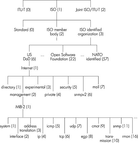
The MODULE-COMPLIANCE construct defines the set of managed objects within a module that an agent must implement. The AGENT-CAPABILITIES construct specifies the capabilities of agents with respect to object- and event-notification definitions. 8.3.2: Management Information Base: MIBAs noted above, the Management Information Base, MIB, can be thought of as a virtual information store, holding managed objects whose values collectively reflect the current "state" of the network. These values may be queried and/or set by a managing entity by sending SNMP messages to the agent that is executing in a managed node on behalf of the managing entity. Managed objects are specified using the OBJECT-TYPE SMI construct discussed above and gathered into MIB modules using the MODULE-IDENTITY construct.The IETF has been busy standardizing the MIB modules associated with routers, hosts, and other network equipment. This includes basic identification data about a particular piece of hardware, and management information about the device's network interfaces and protocols. As of the release of SNMPv3 (mid-1999), there were nearly 100 standards-based MIB modules and an even larger number of vendor-specific (private) MIB modules. With all of these standards, the IETF needed a way to identify and name the standardized modules, as well as the specific managed objects within a module. Rather than start from scratch, the IETF adopted a standardized object identification (naming) framework that had already been put in place by the International Organization for Standardization (ISO). As is the case with many standards bodies, the ISO had "grand plans" for their standardized object identification framework--to identify every possible standardized object (for example, data format, protocol, or piece of information) in any network, regardless of the network standards organization (for example, Internet IETF, ISO, IEEE, or ANSI), equipment manufacturer, or network owner. A lofty goal indeed! The object identification framework adopted by ISO is part of the ASN.1 (Abstract Syntax Notation One) [ISO 1987; ISO X.680 1998] object-definition language that we'll discuss in section 8.4. Standardized MIB modules have their own cozy corner in this all-encompassing naming framework, as discussed below. As shown in Figure 8.3, objects are named in the ISO naming framework in a hierarchical manner. Note that each branch point in the tree has both a name and a number (shown in parentheses); any point in the tree is thus identifiable by the sequence of names or numbers that specify the path from the root to that point in the identifier tree. A fun, but incomplete and unofficial, Web-based utility for traversing part of the object identifier tree (using branch information contributed by volunteers) may be found in [Alvestrand 1997].
At the top of the hierarchy are the International Organization for Standardization (ISO) and the Telecommunication Standardization Sector of the International Telecommunication Union (ITU-T), the two main standards organizations dealing with ASN.1, as well as a branch for joint efforts by these two organizations. Under the ISO branch of the tree, we find entries for all ISO standards (1.0) and for standards issued by standards bodies of various ISO-member countries (1.2). Although not shown in Figure 8.3, under (ISO ISO-Member-Body, a.k.a. 1.2) we would find USA (1.2.840), under which we would find a number of IEEE, ANSI, and company-specific standards. These include RSA (1.2.840.11359) and Microsoft (1.2.840.113556), under which we find the Microsoft File Formats (1.2.840.113556.4) for various Microsoft products, such as Word (1.2.840.113556.4.2). But we are interested here in networking (not Microsoft Word files), so let us turn our attention to the branch labeled 1.3, the standards issued by bodies recognized by the ISO. These include the U.S. Department of Defense (6) (under which we will find the Internet standards), the Open Software Foundation (22), the airline association SITA (69) and NATO-identified bodies (57), as well as many other organizations. Under the Internet branch of the tree (1.3.6.1), there are seven categories. Under the private (1.3.6.1.4) branch, we will find a list [IANA 1999b] of the names and private enterprise codes of more than 4,000 private companies that have registered with the Internet Assigned Numbers Authority (IANA) [IANA 1999]. Under the management (1.3.6.1.2) and MIB-2 branch (1.3.6.1.2.1) of the object identifier tree, we find the definitions of the standardized MIB modules. Whew--it's a long journey down to our corner of the ISO name space! Standardized MIB Modules The lowest level of the tree in Figure 8.3 shows some of the important hardware-oriented MIB modules (system and interface) as well as modules associated with some of the most important Internet protocols. RFC 2400 lists all of the standardized MIB modules. While MIB-related RFCs make for rather tedious and dry reading, it is instructive (that is, like eating vegetables, it is "good for you") to consider a few MIB module definitions to get a flavor for the type of information in a module. The managed objects falling under system contain general information about the device being managed; all managed devices must support the system MIB objects. Table 8.2 defines the objects in the system group, as defined in RFC 1213. Table 8.2: Managed objects in the MIB-2 system group
Table 8.3 defines the managed objects in the MIB module for the UDP protocol at a managed entity. Table 8.3: Managed objects in the MIB-2 udp module
8.3.3: SNMP Protocol Operations and Transport MappingsThe Simple Network Management Protocol Version 2 (SNMPv2) [RFC 1905] is used to convey MIB information among managing entities and agents executing on behalf of managing entities. The most common usage of SNMP is in a request-response mode in which an SNMPv2 managing entity sends a request to an SNMPv2 agent, who receives the request, performs some action, and sends a reply to the request. Typically, a request will be used to query (retrieve) or modify (set) MIB object values associated with a managed device. A second common usage of SNMP is for an agent to send an unsolicited message, known as a trap message, to a managing entity. Trap messages are used to notify a managing entity of an exceptional situation that has resulted in changes to MIB object values. We saw earlier in Section 8.1 that the network administrator might want to receive a trap message, for example, when an interface goes down, congestion reaches a predefined level on a link, or some other noteworthy event occurs. Note that there are a number of important tradeoffs between polling (request-response interaction) and trapping; see the homework problems.SNMPv2 defines seven types of messages, known generically as Protocol Data Units--PDUs, as shown in Table 8.4. Table 8.4: SNMPv2 PDU types
The format of the PDU is shown in Figure 8.4.
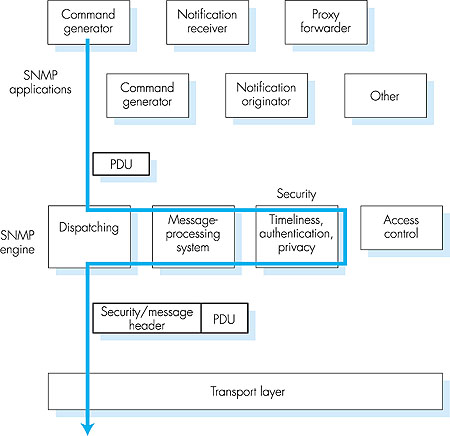
8.3.4: Security and AdministrationThe designers of SNMPv3 have said that "SNMPv3 can be thought of as SNMPv2 with additional security and administration capabilities" [RFC 2570]. Certainly, there are changes in SNMPv3 over SNMPv2, but nowhere are those changes more evident than in the area of administration and security. The central role of security in SNMPv3 was particularly important, since the lack of adequate security resulted in SNMP being used primarily for monitoring rather than control (e.g., SetRequest is rarely used in SNMPv1).As SNMP has matured through three versions, its functionality has grown but so too, alas, has the number of SNMP-related standards documents. This is evidenced by the fact that there is even now an RFC [RFC 2571] that " describes an architecture for describing SNMP Management Frameworks"! While the notion of an "architecture" for "describing a framework" might be a bit much to wrap one's mind around, the goal of RFC 2571 is an admirable one--to introduce a common language for describing the functionality and actions taken by an SNMPv3 agent or managing entity. The architecture of an SNMPv3 entity is straightforward, and a tour through the architecture will serve to solidify our understanding of SNMP. So-called SNMP applications consist of a command generator, notification receiver, and proxy forwarder (all of which are typically found in a managing entity); a command responder and notification originator (both of which are typically found in an agent); and the possibility of other applications. The command generator generates the GetRequest, GetNextRequest, GetBulkRequest, and SetRequest PDUs that we examined in Section 8.3.3 and handles the received responses to these PDUs. The command responder executes in an agent and receives, processes, and replies to (using the Response message) received GetRequest, GetNext Request, GetBulkRequest, and SetRequest PDUs. The notification originator application in an agent generates Trap PDUs; these PDUs are eventually received and processed in a notification receiver application at a managing entity. The proxy forwarder application forwards request, notification, and response PDUs. A PDU sent by an SNMP application next passes through the SNMP "engine" before it is sent via the appropriate transport protocol. Figure 8.5 shows how a PDU generated by the command generator application first enters the dispatch module, where the SNMP version is determined. The PDU is then processed in the message-processing system, where the PDU is wrapped in a message header containing the SNMP version number, a message ID, and message size information. If encryption or authentication is needed, the appropriate header fields for this information are included as well; see RFC 2571 for details. Finally, the SNMP message (the application-generated PDU plus the message header information) is passed to the appropriate transport protocol. The preferred transport protocol for carrying SNMP messages is UDP (that is, SNMP messages are carried as the payload in a UDP datagram), and the preferred port number for the SNMP is port 161. Port 162 is used for trap messages.
We have seen above that SNMP messages are used to not just monitor, but also to control (for example, through the SetRequest command) network elements. Clearly, an intruder that could intercept SNMP messages and/or generate its own SNMP packets into the management infrastructure could wreak havoc in the network. Thus, it is crucial that SNMP messages be transmitted securely. Surprisingly, it is only in the most recent version of SNMP that security has received the attention that it deserves. SNMPv3 provides for encryption, authentication, protection against playback attacks (see Sections 7.2 and 7.3), and access control. SNMPv3 security is known as user-based security [RFC 2574] in that there is the traditional concept of a user, identified by a user name, with which security information such as a password, key value, or access privileges are associated.
|